System Operations Manual
www.paceworldwide.com
Page 4 of 40
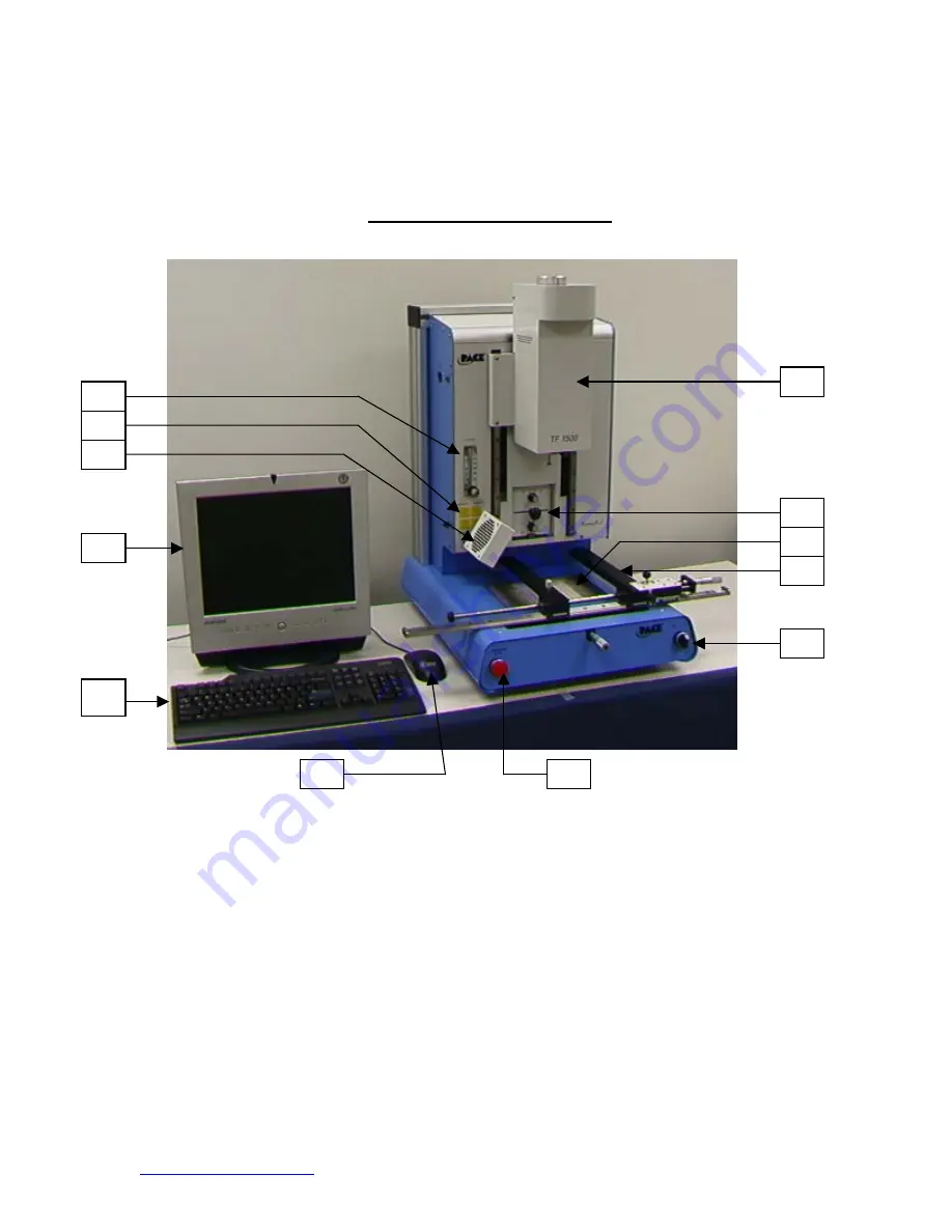
TF 1500 Parts Identification
Figure 1
A. Air Flow Meter
This device is used to control and monitor the airflow
through the reflow head.
B. Sensor Input
The sensor inputs are K-type thermo-couples.
Measured temperatures are displayed through the PC
software in real time for use in making profile graphs.
C. Cooling Fan
The component and PCB are cooled by the cooling fan,
which can be set to activate automatically after the
reflow cycle is complete or operated manually.
D. LCD Display Monitor
Displays PC software.
E. Keyboard
Used to enter information into software.
F. Reflow Head
Contains the top-side heater and moves up and down
via an electric motor that is controlled through the
software. The reflow head is clutched to prevent
excessive downward force from being applied.
A
B
C
D
E
F
G
H
I
J
K
L


