©2013 PACE Inc., Southern Pines, NC
Page 20 of 31
All Rights Reserved
4. Press the Menu button once. This will toggle you to the Settings column. At this point the
Temp LED will be flashing.
5. Press the Select Button once.
6. Now select the desired temperature with the Scroll Keys (
). Press and hold the desired
key; observe the Digital Readout as the Set Temperature increases (or decreases) in 1° and
then 10° increments as the key is held. Press the Select Button when complete.
7. Next, press the Scroll Down Button (
) once. The
Blower Speed LED will now be flashing.
8. Press the Select Button and select the blower speed
(1-9) by using the Scroll Keys (
). Press the Select
Button when complete.
9. Press the Scroll Down Button (
) again; the Time LED will now be illuminated.
10. Press the Select Button and adjust the Cycle Time as desired using the Scroll Keys (
).
Press and hold the desired key; observe the Digital Readout as the Set Temperature
increases (or decreases) in 1 second and then 10 second increments as the key is held.
Press the Select Key when finished to save the selections.
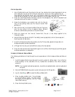
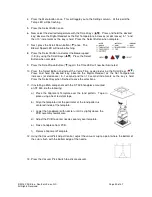
11. If installing a BGA component with the ST 325 handpiece mounted
on ST 500, do the following:
a) Place the Alignment Template over the land pattern. Tape in
place using a heat resistant tape.
b) Align the template until the perimeter of the land pattern is
centered inside of the template.
c) Lower the handpiece (with nozzle) until it is slightly above the
PCB assembly rework area.
d) Adjust the PCB to center nozzle squarely over template.
e) Raise handpiece from PCB.
f) Remove Alignment Template.
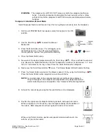
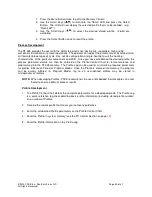
12. Using the Vacuum Pick Adjust Control, adjust the vacuum cup to a point where the bottom of
the cup is flush with the bottom edge of the nozzle.
13. Press the Vacuum Pick Switch to activate vacuum.


