©2013 PACE Inc., Southern Pines, NC
Page 15 of 31
All Rights Reserved
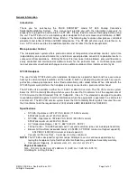
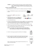
6. Now select the desired temperature with the Scroll Keys (
). Press and hold the desired
key; observe the Digital Readout as the Set Temperature increases (or decreases) in 1° and
then 10° increments as the key is held. Press the Select Button when complete.
NOTE:
The minimum temperature is 149°C (300°F) and the maximum temperature is 482°C
(900°F).
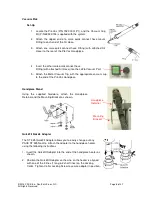
7. Next, press the Scroll Down Button (
) once. The Blower Speed LED will now be flashing.
8. Press the Select Button and select the blower speed (1-9 or 5-20 SLPM) by using the Scroll
Keys (
). Press the Select Button when complete to save the selections.
9. If using a Single Jet Nozzle, no vacuum cup is used; proceed to step 14.
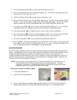
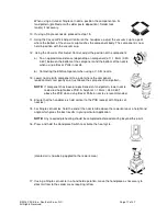
10. Using the Vacuum Pick Adjust Control, adjust the vacuum cup to a point
where the bottom of the vacuum cup is flush with the bottom edge of the
nozzle.
11. Hold the handpiece vertical to the PCB.
12. Lower the nozzle:
a) To an approximate distance of 1mm (.040”) above the PCB when using a
Box nozzle.
b) To an approximate distance of (depending on component) 1mm (.040”)
above the PCB when using a Pattern nozzle.
c) Contacting the BGA component when using a V-A-N nozzle.
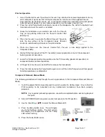
13. Press and release handpiece Vacuum Cycle Switch to activate vacuum.
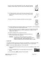
14. For Single Jet nozzles, hold the end of the nozzle tube above the
rework area at a height and angle which gives the best results in
your particular application.
15. Press and hold the Handpiece Cycle Switch to activate the heat cycle.
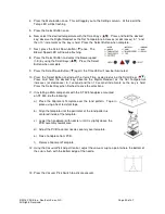
16. When complete solder melt is observed, gently lift the handpiece to
remove the component from the PCB. When using a Curved, Single Jet
nozzle, use a vacuum pickup device or tweezers to lift the component
from the PCB; steps 17 & 18 are not used.
17. Position the nozzle (with component) over a heat resistant surface.
18. Press and hold the Vacuum Cycle Switch for 0.5 second (minimum) to deactivate vacuum
and release component.


