©2013 PACE Inc., Southern Pines, NC
Page 19 of 31
All Rights Reserved
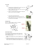
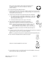
Lower the nozzle to a point approximately 1mm (.040”) above the PCB when
using Box or Pattern nozzles. Lower the nozzle to contact a BGA component.
14. For Single Jet nozzles, hold the end of the nozzle tube above the rework
area at a height and angle which gives the best results in your particular
application.
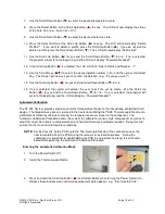
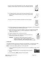
15. Press and release the handpiece Cycle Switch to activate heat cycle.
16. The LCD will display the remaining cycle (“Reflo”) time counting down. At 5 seconds before
the end of cycle, the vacuum will automatically activate.
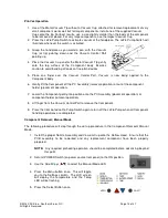
17. At the end of the cycle, gently lift the handpiece to remove the component from the PCB.
When using a Single Jet nozzle, use a vacuum pickup device or tweezers to lift the
component from the PCB.
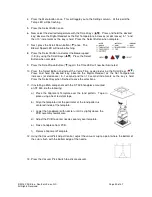
18. Position the component over a heat resistant surface.
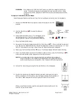
19. Depress and hold the Vacuum Pick Switch for 0.5 second (minimum) to
deactivate vacuum and release component.
WARNING:
The component is HOT! DO NOT remove or catch the
component with bare hands. Allow the component to drop onto
the heat resistant surface. Allow sufficient time for the
component and PCB to cool to room temperature before handling.
Timed Install
The following procedure will step you through the set up procedure in the Timed Install mode.
Installation times can be determined by visual solder melt or by the use of a thermocouple.
NOTE:
For best results, begin by adding 10% to the removal time.
1. Install the proper Nozzle Assembly and Vacuum Cup (if not using Single Jet nozzle) onto the
handpiece.
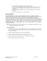
2. Set the unit POWER Switch (on front panel of power source) to the ON
position.
3. Use the Scroll Keys (
) to select the Timed Install LED.


