background image

©2013 PACE Inc., Southern Pines, NC 

Page 31 of 31 

All Rights Reserved 

PACE  Incorporated  retains  the  right  to  make  changes  to  specifications  contained  herein  at  any  time, 
without notice.  Contact your local authorized PACE Distributor or PACE Incorporated to obtain the latest 
specifications. 
 
The following are trademarks and/or service marks of PACE, Incorporated, MD, USA: 
 

INSTACAL

,  FUMEFLO

,  HEATWISE

,  PACEWORLDWIDE

,  PERMAGROUND

POWERPORT

,  POWERMODULE

,  TEMPWISE

,  TIP-BRITE

,  AUTO-OFF

,


and


TEKLINK

 
The following are registered trademarks and/or service marks of PACE Incorporated, Annapolis Junction 
Maryland U.S.A.   
 

ARM-EVAC

,  FLO-D-SODR

,  MINIWAVE

,  PACE

,  SENSATEMP

,  SNAP-VAC

SODRTEK

,  SODR-X-TRACTOR

,  ST  325

,  THERMOJET

,  THERMOTWEEZ

VISIFILTER

, THERMO-DRIVE

®

, and TOOLNET

®

 
PACE  products  meet  or  exceed  all  applicable  military  and  civilian  EOS/ESD,  temperature  stability  and 
other specifications including MIL STD 2000, ANSI/JSTD 001, IPC7711, and IPC A-610. 


www.paceworldwide.com 

PACE Incorporated 


Pace Europe 

255 Air Tool Drive 


11 Holdom Avenue 

Southern Pines,  


Bletchley, Milton Keynes, 

North Carolina, 28387   

United Kingdom, MK1 1QU 

Tel:  (877) 882-PACE   

Tel:  011 44 1908 277666 

Tel:  (910) 695-7223 


Fax: 011 44 1908 277777 

Fax: (910) 695-1594 


Содержание SODRTEK ST 325

Страница 1: ...Operation and Maintenance Manual for the SODRTEK ST 325 Digital Convective Soldering Desoldering System P N 5050 0537 ...

Страница 2: ...nstallation 10 Definitions 10 System Power Up 11 Set Up Mode 11 Automatic Calibration 12 Operation 13 Password 13 Front Panel Selections 13 Pik Vak Operation 14 Component Removal Manual Mode 14 Component Installation Manual Mode 16 Timed Removal 18 Timed Install 19 PC Control 22 Memory 22 Save 22 Recall 22 Process Development 24 Profile Development 24 General Process Guidelines 26 Board Preparatio...

Страница 3: ...justing vacuum pick has a push pull action allowing components to be lifted automatically after solder reflow When utilized with the ST 325 System work platform the handpiece is easily converted to a precision reflow head The ST 325 unit is available in either the 115 VAC or 230 VAC version The 115 VAC version system bears the FCC Conformity Marking which assures the user that it conforms to all t...

Страница 4: ...rts Identification Power Switch Scroll Keys Menu Key Select Key K type Thermocouple Receptacle LCD Display Earth Ground Receptacle AC Power Receptacle Fuse RS 232 PC Input Pre Heater Receptacle ST 450 Remote Controller Receptacle Fuse LoFlo Pump Switch LoFlo Vacuum Port ...

Страница 5: ...ACUUM PICK ADJUST CONTROL Provides adjustment for height of Vacuum Pick Assembly Vacuum Cup Turn clockwise to raise pick or counterclockwise to lower pick VACUUM PICK ASSEMBLY Provides a means to lift or place components HEAT SHIELD Protects the operator from unintentional contact with the heater VACUUM CUP Provides positive holding of components for positioning during the replacement process and ...

Страница 6: ...amage to equipment and represent a potential for serious personnel injury DANGER Defines additional information that if not closely followed might result in severe personnel injury or death Danger is not used for property damage unless personal injury risk is present Usage Warnings Cautions WARNINGS 1 A fire hazard may arise if the ST 325 is used improperly 2 Do not use the ST 325 in the presence ...

Страница 7: ...sonnel must understand and follow when using or servicing this product These precautions may or may not be included elsewhere in this manual Safety Electrical Requirements The ST 325 unit draws approximately 575 Watts which is listed on the nameplate on the power source rear panel A separate dedicated AC supply line circuit may be required to adequately power the unit system If your power outlet c...

Страница 8: ...tach the Metal Vacuum Tip with the appropriate vacuum cup to the end of the Pik Vac Handpiece Handpiece Stand Using the supplied hardware attach the Handpiece Retainer and the Mounting Bracket as shown QuickFit Nozzle Adapter The ST 325 QuickFit Adapter allows you to easily change out any PACE ST 325 Nozzle Attach the adapter to the handpiece heater using the following instructions 1 Insert the Qu...

Страница 9: ...sides of the component e g SOICs Single Jet Nozzles Available in straight curved and flat end versions these nozzles are used for removal replacement of small surface mount components e g chip components small QFPs Land Grid Arrays e g those used on pagers cellular telephones or for reflowing solder on single solder connections Template Selection Alignment Templates are used as an aid in aligning ...

Страница 10: ...cycle where air is flowing through the handpiece Password The password feature when activated will prevent unauthorized alteration of stored system parameters If a password has been installed the Digital Readout will display an instruction to enter the password a 4 key numerical sequence stored in Set Up Mode when a setting change is attempted Preheat A preliminary process in which the work is hea...

Страница 11: ...e provides the option to select from the following items 1 Password Entry 2 Temperature scale selection C or F 3 Auto Vac 4 Deletion of profiles 1 Turn Power Switch Off 2 Turn the ST 325 On while holding the Menu Button Release the Menu Button when the LCD displays the Development Date e g Dev 4 06 04 The LCD will now display Password Needed if there is no password currently stored in the system I...

Страница 12: ... up mode Use the Scroll Up Button for yes and the Scroll Down Button for no If no is selected the program will cycle to the beginning and the LCD will display Password Needed Automatic Calibration The ST 325 System provides precision control of temperature thanks to the closed loop controlled circuit design The temperature sensor is located in the heater but utilizing the PACE Thermocouple Nozzle ...

Страница 13: ...aved by pressing the Up Button or the Offset Calibration Mode may be exited by pressing the Vacuum Button on the handpiece Either selection will exit the Offset Calibration Mode and place the system into the previously used menu for regular operation NOTE If during the procedure the LCD displays Auto Cal Error repeat the Auto Calibration Procedure again Operation The PACE ST 325 unit is easy to op...

Страница 14: ...onent body 6 Gently lift the Component off the PC Assembly removal operation or out of the component holder placement operation 7 Lower the Component gently into position onto the PC Assembly placement operation or component holder removal operation 8 Lift finger from the Vacuum Control Port to release the Component 9 Press the Illuminated LoFlo Pump Switch again to turn off the LoFlo Pump when al...

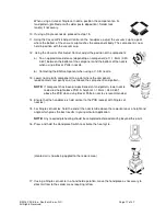
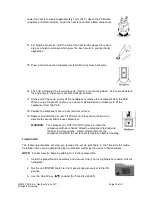
Страница 15: ...tom edge of the nozzle 11 Hold the handpiece vertical to the PCB 12 Lower the nozzle a To an approximate distance of 1mm 040 above the PCB when using a Box nozzle b To an approximate distance of depending on component 1mm 040 above the PCB when using a Pattern nozzle c Contacting the BGA component when using a V A N nozzle 13 Press and release handpiece Vacuum Cycle Switch to activate vacuum 14 Fo...

Страница 16: ...old the desired key observe the Digital Readout as the Set Temperature increases or decreases in 1 and then 10 increments as the key is held Press the Select Button when complete 6 Next press the Scroll Down Button once The Blower Speed LED will now be flashing 7 Press the Select Button and select the blower speed 1 9 by using the Scroll Keys Press the Select Button when complete to save the selec...

Страница 17: ...component when using a V A N nozzle 13 Lower nozzle with component to a point where the component leads contacts rest gently on or just above the component land pattern NOTE If component has been pre positioned on land pattern lower nozzle to desired height above PCB A height of 1 1 5mm 040 060 above the PCB when using Box or Pattern nozzles is recommended 14 Ensure that the handpiece is held vert...

Страница 18: ... the desired temperature with the Scroll Keys Press and hold the desired key observe the Digital Readout as the Set Temperature increases or decreases in 1 and then 10 increments as the key is held Press the Select Button when complete 7 Next press the Scroll Down Button once The Blower Speed LED will now be flashing 8 Press the Select Button and select the blower speed 1 9 by using the Scroll Key...

Страница 19: ...r tweezers to lift the component from the PCB 18 Position the component over a heat resistant surface 19 Depress and hold the Vacuum Pick Switch for 0 5 second minimum to deactivate vacuum and release component WARNING The component is HOT DO NOT remove or catch the component with bare hands Allow the component to drop onto the heat resistant surface Allow sufficient time for the component and PCB...

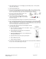
Страница 20: ...n and adjust the Cycle Time as desired using the Scroll Keys Press and hold the desired key observe the Digital Readout as the Set Temperature increases or decreases in 1 second and then 10 second increments as the key is held Press the Select Key when finished to save the selections 11 If installing a BGA component with the ST 325 handpiece mounted on ST 500 do the following a Place the Alignment...

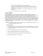
Страница 21: ...st the height of the component relative to the nozzle as desired PACE recommends that a The bottom of the nozzle should be positioned approximately 1mm 0 040 above the PCB when using Box or Pattern nozzles b BGA components are to be positioned fully into the nozzle The walls of the V A N nozzles will contact the component body 16 Lower nozzle with component to a point where the component leads con...

Страница 22: ...urchased to utilize the Remote PC Control The software further allows the ST 325 to control the ST 450 Preheater when bottom side heating of the PC is required This manual will include the setup information for the ST 450 Pre Heater See manual 5050 0546 for further details Memory Save The following procedure will step you through the profile Save procedure in the Memory Column This can be accessed...

Страница 23: ...ocess parameter details can then be entered on the Profile Control Chart for future reference and programmed into the ST 325 memory The Profile Log can be used for summarizing required parameters for profiles in Manual Timed or Program Modes Once the Profile is entered into memory the program can be quickly initiated in Program Mode Up to 20 user defined profiles may be stored in microprocessor me...

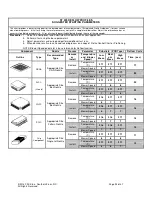
Страница 24: ...er Speed parameter is base reference for Reflow function Component Nozzle Process Parameter Substrate PCB Type Reflow Cycle Outline Type Recommended Type Remove or Install Temperature and Blower Speed Low Mass Medi um Mass High Mass Time sec Temperature C 371 371 371 Remove Blower Speed 5 5 5 77 Temperature C 371 371 371 PBGA Appropriate Size V A N Nozzle Install Blower Speed 3 3 4 90 Temperature ...

Страница 25: ...ROFILE CONTROL CHART Profile Component Temp Scale F C Process Remove Install PCB Designation Preheat Yes No Top Preheat Yes No Lower Preheat Yes No Time Time Temp Temp Start sec Blower Speed Soak Yes No Temp Time sec Blower Speed Reflow Yes No Temp Time sec Blower Speed Install Only Vacuum Release Lower Pump On Off Cool Down On Off Approved By Time sec Blower Speed Date Comments Instructions ...

Страница 26: ...nd pattern as per your company specifications The most widely used methods are as follows 1 Prefill The PCB land pattern is prefilled using a soldering iron Care must be taken to insure that all lands are tinned with an equal deposition of solder provides a uniform appearance 2 Solder Paste Apply an equal amount of solder paste on each land Take care to insure that the proper amount of paste is di...

Страница 27: ...hout the soldering process Preheating Preheating of a printed circuit assembly is recommended in the repair process when one or more of the following situations exist 1 Epoxy glass substrate with 4 or more layers 2 Substrate with large ground planes 3 Substrate of ceramic polyimide or other high heat dissipative material 4 Printed circuit assembly with large metal heat sinks Preheating of assembli...

Страница 28: ...mbly Blower Run Error The power source blower unit is not running Contact PACE for assistance Power Source Handpiece Refer to the table below Most malfunctions are simple and easy to correct Symptom Probable Cause Solution Blown Fuse Inspect and replace the fuse s located on the power source rear panel No power to system Line cord unplugged Plug line cord into the appropriate AC outlet Heater Asse...

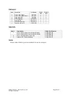
Страница 29: ...2 0093 0 1 5 PV 65 Handpiece 7027 0001 P1 1 1 6 Nozzle Adapter 4028 0001 P1 1 1 7 Hot Grip Removal Pad 1100 0307 P1 1 1 8 Operations Manual CD CD5050 0459 1 1 Spare Parts Item Description PACE Part Number Fuse 7 Amp 125 V Fast Acting ST 325 1159 0267 P5 1 Fuse 5 Amp 250 V Fast Acting ST 325E 1159 0266 P5 2 Fuse 0 5 Amp 250 V Time Lag 1159 0213 P5 3 Optional PC Control Software 1199 0019 P1 Service...

Страница 30: ...ly to all persons and entities SELLER MAKES NO OTHER WARRANTY EXPRESS OR IMPLIED AND MAKES NO WARRANTY OF MERCHANTABILITY OR FITNESS FOR A PARTICULAR PURPOSE Seller will at its option repair or replace any defective products at its facility or other location approved by it at no charge to user or provide parts without charge for installation by the user in the field at user s expense and risk User...

Страница 31: ... are registered trademarks and or service marks of PACE Incorporated Annapolis Junction Maryland U S A ARM EVAC FLO D SODR MINIWAVE PACE SENSATEMP SNAP VAC SODRTEK SODR X TRACTOR ST 325 THERMOJET THERMOTWEEZ VISIFILTER THERMO DRIVE and TOOLNET PACE products meet or exceed all applicable military and civilian EOS ESD temperature stability and other specifications including MIL STD 2000 ANSI JSTD 00...

Отзывы: