DESCRIPTION OF WINCH
The winch has four basic component parts:
1. Winch base
2. Hydraulic motor and brake valve
3. Brake cylinder and motor support
4. Drum assembly
The drum assembly consists of three basic assemblies:
1. Drum with integral ring gear
2. Output planetary gear set
3. Primary planetary gear set
The hydraulic motor is bolted to the motor support
which in turn is bolted to the brake cylinder and the
base. The motor end of the drum, running on a ball
bearing, is supported by the brake cylinder. The other
end of the drum runs on a ball bearing on the support
bolted to the base. The ring gear for both planetary sets
is machined into the drum’s inside surface.
WINCH OPERATION
The hydraulic motor drives the sun gear of the primary
planetary gear set through the splined inner race of the
brake clutch. When driven by the sun gear, the primary
planet gears walk around the ring gear in the drum and
drive the primary planet carrier.
The primary planet carrier drives the output planet sun
gear which, in turn drives the output planet gears. The
output planet carrier is splined to the bearing support
and cannot rotate. Therefore, as the output planet gears
are driven by the sun gear, they will drive the ring
gear/drum.
D
UAL
B
RAKE
S
YSTEM
– D
ESCRIPTION
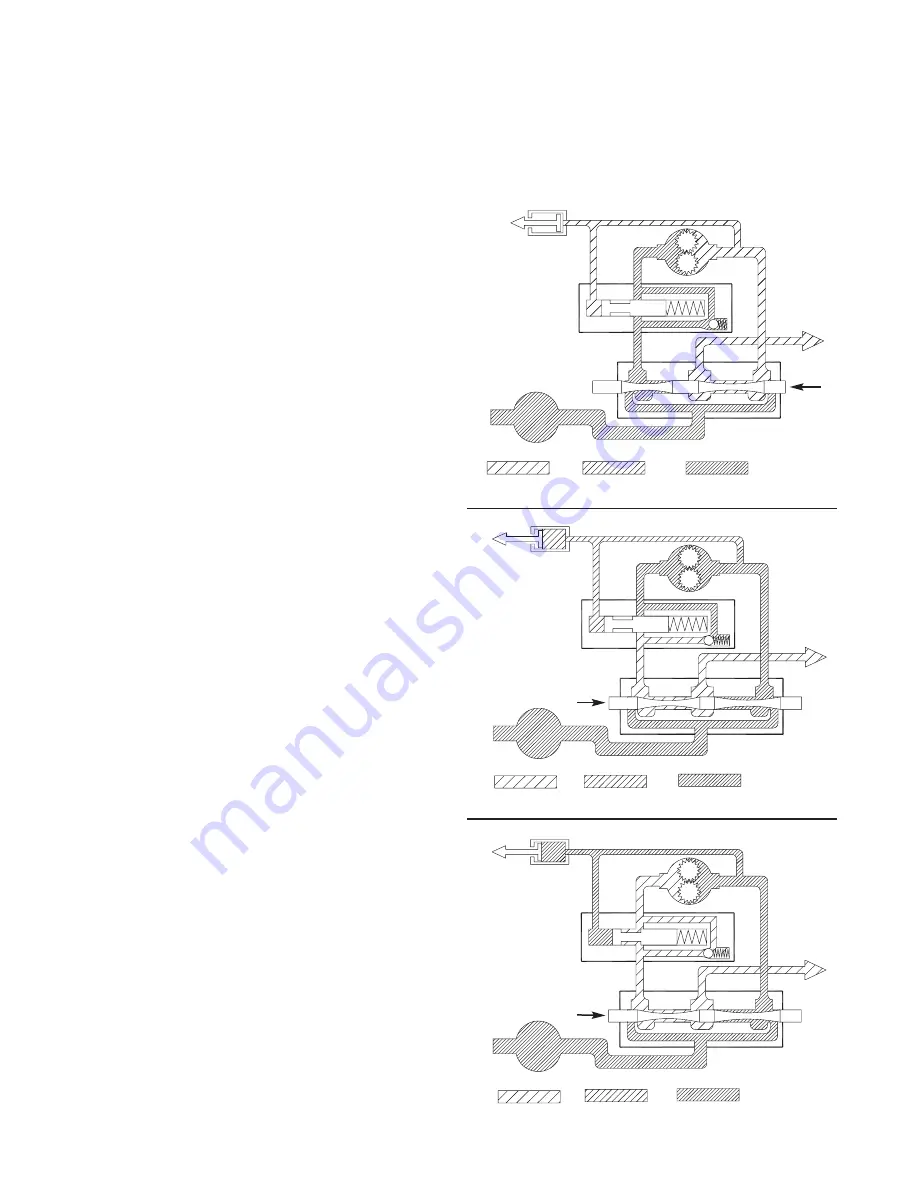
The dual brake system consists of a dynamic brake sys-
tem and a static brake system.
The dynamic brake system has two operating compo-
nents:
1. Brake valve assembly
2. Hydraulic motor
The brake valve is basically a counterbalance valve. It
contains a check valve to allow free flow of oil to the
motor in the hoisting direction and a pilot operated,
spring-loaded spool valve that blocks the flow of oil out
of the motor when the control valve is placed in neutral.
When the control valve is placed in the lowering posi-
tion, the spool valve remains closed until sufficient pilot
pressure is applied to the end of the spool to shift it
against spring pressure and open a passage. After the
spool valve cracks open, the pilot pressure becomes
flow-dependent and modulates the spool valve opening
which controls the lowering speed.
Figures 2, 3 & 4 show a simplified version of the brake
valve for illustrative purposes.
The static brake system has three operating compo-
nents:
1. Spring Applied, Multiple Friction Disc Static Brake
2. Brake Clutch Assembly
3. Hydraulic Piston and Cylinder
4
THEORY OF OPERATION
Pump
Brake
Valve
Static
Brake
Motor
Control
Valve
Low Pressure Medium Pressure High Pressure
To
Tank
Figure 3
Pump
Brake
Valve
Static
Brake
Motor
Control
Valve
Low Pressure Medium Pressure
High Pressure
To
Tank
Figure 2
Pump
Brake
Valve
Static
Brake
Motor
Control
Valve
Low Pressure Medium Pressure High Pressure
To
Tank
Figure 4
Содержание BRADEN H20R
Страница 27: ...26 BRADEN H20R 05559 COMPONENTS ...


