background image

INLINE MOUNT Exhaust Brakes


I N S T A L L A T I O N   M A N U A L  

-   L 2 0 3 1

P G .   7

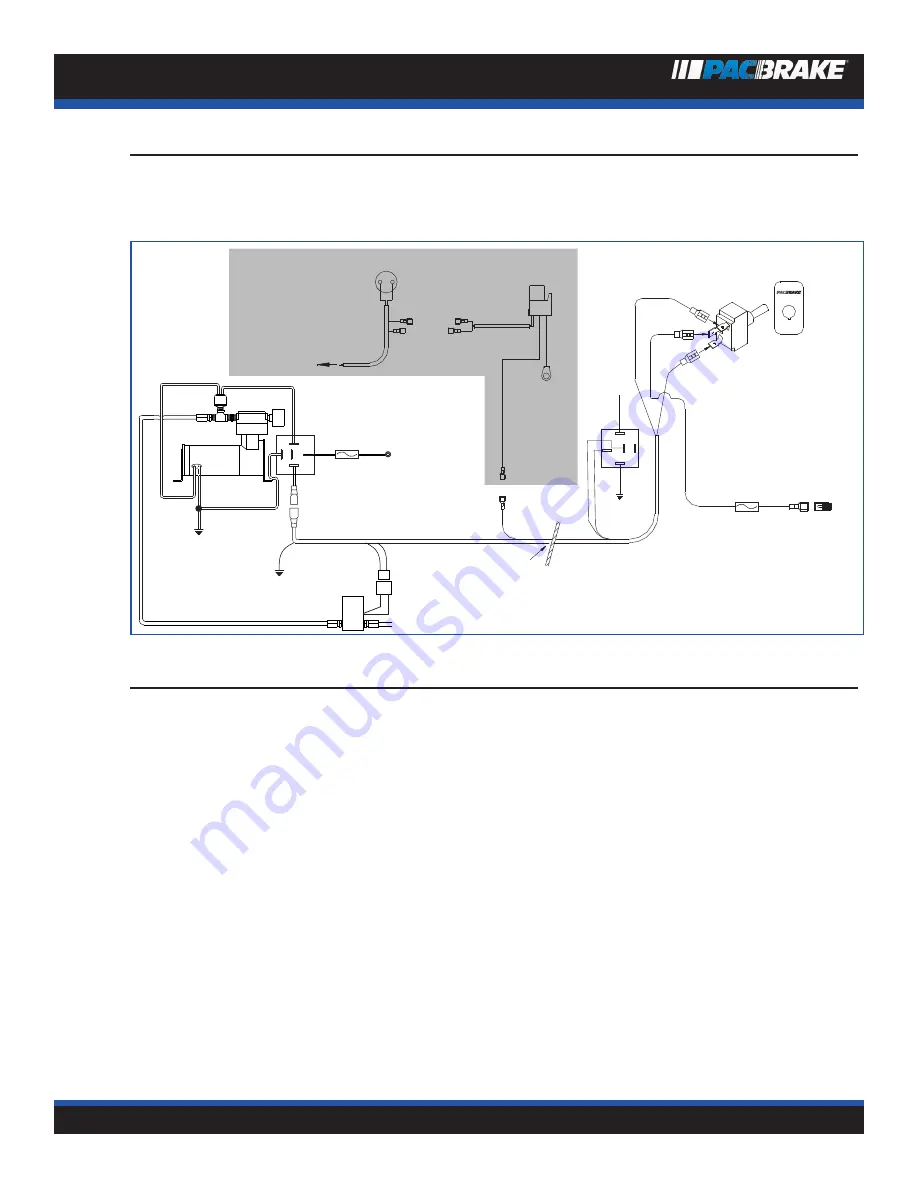
E X H A U S T   B R A K E   W I R I N G   S C H E M A T I C

1998-2002 Ford Trucks and Econoline Vans 

Equipped With Powerstroke

Ford® Brake Pressure switch 

Blk./Yel. 

Blue 

Red 

Dash 

switch 

OFF 

Red 

Red 

Red 

Red 

To IVS 

Ground 

Red 

Black 

15 Amp 

Fuse 

12V+ 

Ignition 

Switched 

Green 

Black 

Firewall 

Blk./Yel. 

To Ford® PCM 

Blue 

Cruise 

Relay  

Green 

NOTE:  

SHADED AREA 

APPLIES TO 

CRUISE 

CONTROL 

VEHICLES 

86  87 

85 

30  87a 


Red 

Ground 

Relay 

Air Intake 

Filter 

20 Amp 

Fuse 

Connect to 

positive battery 

terminal 

87 

30 

87a 

85 

86 

Black 

Yellow 

Red 

Green 

To Brake 

Green 

T H R O T T L E   R E L A Y   I N S T A L L A T I O N

At the throttle pedal, locate the I.V.S. (Idle Validation Switch).

NOTE: The IVS connection is critical and must be correct. We recommend using a 12 volt test light to verify the cor-
rect wire BEFORE installing the “T” tap.


Most common for vehicles built after 10/2000 is a red wire with a green stripe 2nd from the top of the connector, however because 
of possible production changes, using a test light is the only way to be sure. With the ignition on, probe this wire with the test light 
first as it should be 12 volt positive with the accelerator pedal to the floor. Release the pedal and the light should go off. If this is 
correct connect this wire as explained below, if not, probe the remaining wires until you locate the one which has 12 volts positive 
with the accelerator pedal depressed and no current with the pedal released.
With the correct wire selected, use the blue electrical “T” tap supplied and tap into this wire. Plug the insulated male end of the 12” 
yellow wire into the “T” tap. Connect the opposite end of the yellow wire to terminal 86 of the supplied relay. Connect the 12” black 
wire to terminal 85 of the relay and find a good vehicle ground for the eye terminal on the opposite end.
Connect the two red harness wires to terminals 30 and 87A and then secure the relay to existing wiring (in this location) with the 
tystraps provided.

Содержание Inline Mount

Страница 1: ......

Страница 2: ...er I D before cutting the exhaust pipe 1 With the exhaust brake on the bench loosely attach the ex haust pipe adapters provided and make a measurement to determine the length of vehicle exhaust pipe t...

Страница 3: ...his time to ensure the joint cannot separate or leak under pres sure 4 If removed reinstall the front section of pipe on the engine Torque turbo clamp to engine manufacturers specification Center brak...

Страница 4: ...sleeves provided These will isolate the compressor from vibration NOTE A remote breather kit for compressor intake air must be used if dust or road spray is present near the air intake filter Pacbrake...

Страница 5: ...st brake back pressure Pacbrake test gauge kit PT C10600 can be purchased through the Pacbrake distribution system This kit contains all the necessary parts to perform back pressure tests The gauge us...

Страница 6: ...AT I O N M A N U A L L 2 0 3 1 P G 6 C10600 Test Gauge Kit 1 2 3 4 5 6 must be ordered separately Illus No Part No Description Qty 1 C10650 Gauge 1 2 C10800 Hose 1 3 C10678 Fitting 1 4 C10677 Steel Tu...

Страница 7: ...uilt after 10 2000 is a red wire with a green stripe 2nd from the top of the connector however because of possible production changes using a test light is the only way to be sure With the ignition on...

Страница 8: ...ss Neatly secure all wiring with the plastic ties Connect the wiring harness to the solenoid and to the cruise relay 3 Remove the lower instrument panel see arrow Drill a 1 2 hole as shown for the das...

Страница 9: ...werstroke Ford Brake Pressure switch Blk Yel Blue Red Dash switch OFF Red Red Red Red Red Black 15 Amp Fuse 12V Ignition Switched Green Black Firewall Blk Yel To Ford PCM Blue Cruise Relay Green NOTE...

Страница 10: ...lue wires coming from the relay Replace the engine top cover and neatly secure all wiring with the plastic ties 3 Drill a 1 2 hole through the firewall above the throttle switch and below the clutch m...

Страница 11: ...place panel Check Operation Start engine and turn Pacbrake on engine will idle with Pacbrake engaged Advance the throttle from idle to approximately 1200 RPM and back to idle several times ensuring th...

Страница 12: ...a 85 86 20 Amp Fuse Connect to positive battery terminal NOTE Pacbrake wiring kit contains toggle type switch source Navistar rocker switch part number 1677051 C1 if desired The NavPak ECM requires ex...

Страница 13: ...y receptacle with the green ground terminal under the screw head Install relay Route the loomed yellow wire through the firewall grommet into the cab to be connected to the dash switch later 2 E C M C...

Страница 14: ...F S W I T C H I N S T A L L AT I O N Switch location can vary depending on customer choice or the availability of space Choose a location which is convenient to the driver Pacbrake offers a gear lever...

Страница 15: ...on power supply 1988 to 1993 models use medium blue 12 gauge wire rear of the fuse panel 1994 to 1997 models use medium blue 14 gauge 1998 models use black with orange trace Install the t tap connecto...

Страница 16: ...ud nut and tighten making sure the switch arm is behind the accelerator lever Adjust the switch by loosening the screws and positioning it to click as the throttle returns to it s released posi tion C...

Страница 17: ...a 19594 96 Ave Surrey BC V4N 4C3 USA 250 H St Box 1822 Blaine WA 98231 1822 Pacbrake exhaust brakes are protected by law U S patents 5 445 248 Patents pending Pacbrake and Direct Mount are registered...

Отзывы: