INLINE MOUNT Exhaust Brakes
I N S T A L L A T I O N M A N U A L
- L 2 0 3 1
P G . 1 6
E N G I N E C O M P A R T M E N T
Connect the yellow wire from the cab to the remaining relay
wire using the splice connector supplied in the kit.
Secure all wiring and hoses away from heat sources and
moving parts.
T H R O T T L E S W I T C H I N S T A L L A T I O N
1 9 8 8 t o 1 9 9 3
Remove dash panel below steering column to access fuse
panel.
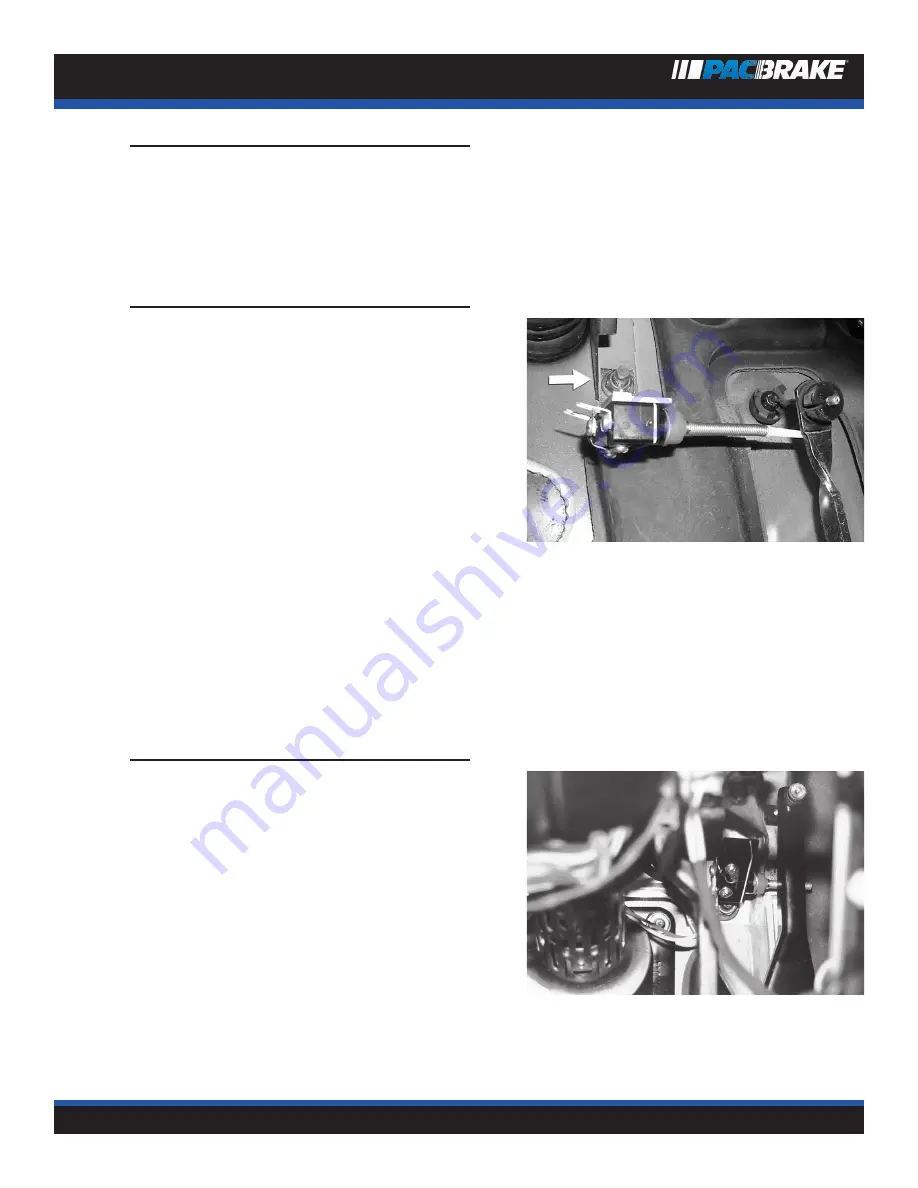
Locate stud shown in the photo and remove nut.
The header pipe kit contains an alternate throttle switch
bracket for pre-1994 vehicles.
Remove the switch from the bracket supplied in the main kit
and install on the alternate bracket.
Install the throttle switch assembly with the switch arm
horizontal. Reinstall the stud nut and tighten, making sure
the switch arm is behind the accelerator lever.
Adjust the switch by loosening the screws and positioning
it to “click” as the throttle returns to it’s released posi-
tion. Cycle the throttle and listen for the click each time the
throttle returns to idle. Tighten screws when adjustment is
complete.
Connect wires as shown in schematic page 16.
T H R O T T L E S W I T C H I N S T A L L A T I O N
( 1 9 9 4 A N D N E W E R )
Remove dash panel below steering column.
Locate the stud shown here and remove the nut.
Install the throttle switch assembly with the switch arm
horizontal.
Reinstall the stud nut and tighten, making sure the switch
arm is behind the throttle lever.
Adjust the switch by loosening the screws and positioning
it to “click” as the throttle returns to its released position.
Cycle the throttle and listen for the click sound each time
the throttle returns to idle.
Connect wires as shown in schematic page 16.
Содержание Inline Mount
Страница 1: ......


