Instruction Manual
Updated11/2013
9
| 24
4.3 electrical components
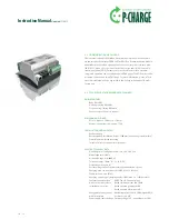
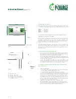
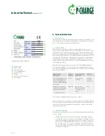
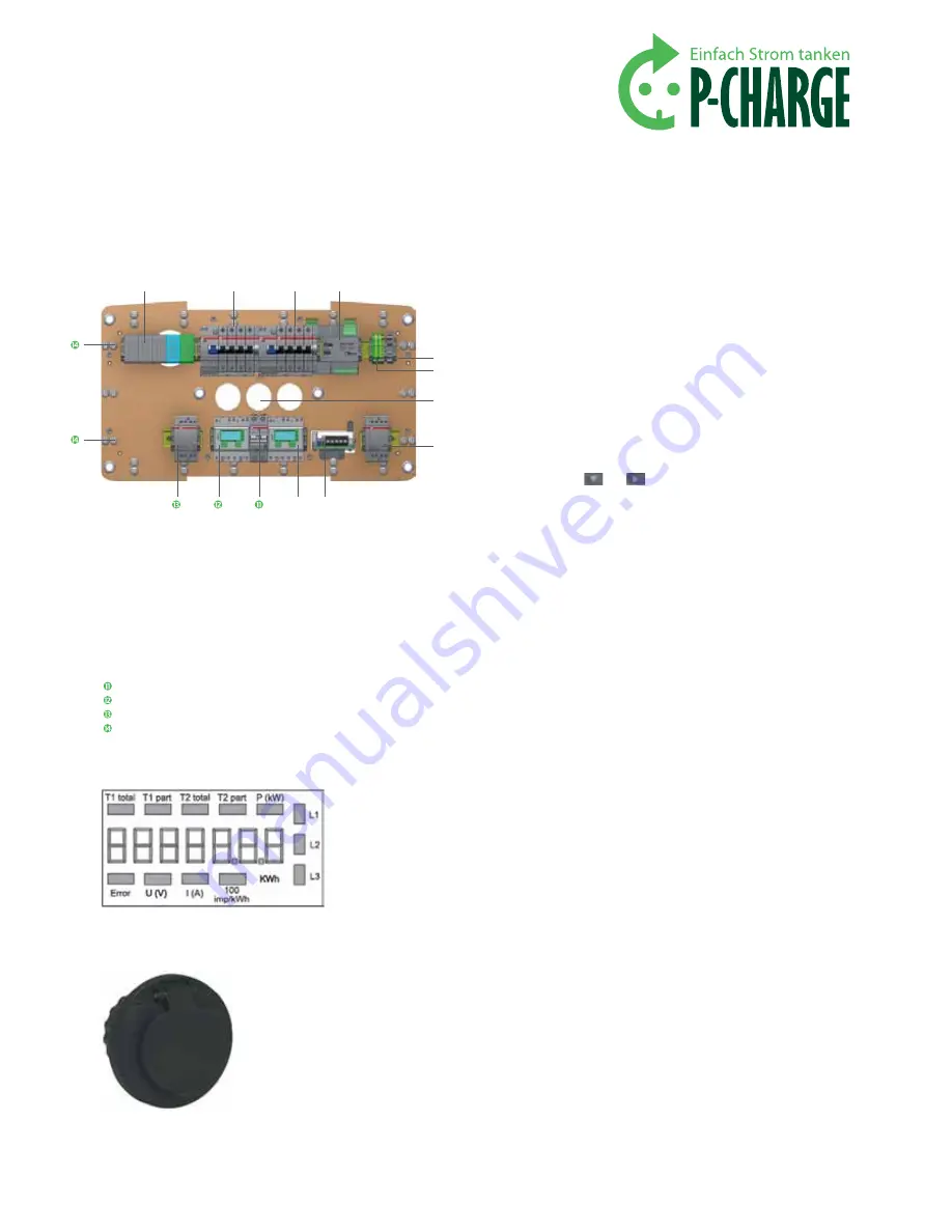
The following image of the carrier plate presents an overview of the electronic
components implemented. You will get this view, if you remove the cover of
the Wallbox, loosen the 8 screws from the housing and work the housing off
to the front. The housing cover hangs securely on the strain relief devices and
thus protects the cabling of the Wallbox.
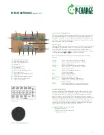
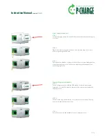
Digital meter
Integrated digital meters present various options for the control of the energy
consumption of the Wallbox. As well as electrical energy consumed in kWh,
the current values for voltage, current and output are displayed both in
individual phases and as an overall total. Navigation through the meter menu
is with the arrow keys
and
on the front of the meter.
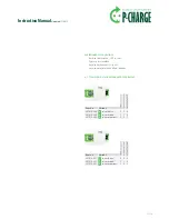
Here is an explanation of the meter functionality and of the individual
displays.
t1total:
Shows total energy consumption for Tariff 1
t1part:
Shows partial energy consumption for Tariff 1;
this value can be reset
t2total:
Shows total energy consumption for Tariff 2
t2part:
Shows partial energy consumption for Tariff 2;
this value can be reset
p(kW):
Shows current output per phase or
of all phases together
u(v):
Shows voltage per phase
i(a):
Shows current per phase
100 imp/kWh:
Pulsation according to output
kWh:
Consumption is displayed in kWh units
l1 / l2 / l3:
With P-, U-, I- or error message the relative
phase is displayed
error:
With missing phases or incorrect current direction.
The corresponding phase is additionally displayed.
4.4 socket eQuipment
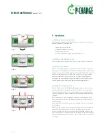
In its basic design, the P-CHARGE Wallbox is fitted with 2 x IEC 62196-2 Type
2 charging sockets. These sockets enable charging of an electric vehicle in
accordance with IEC 61851-1 Mode 3. The Wallbox communicates with the
vehicle via signal contacts PP and CP. Each charging outlet has a separate
RCBO, active energy meter and contactor. The charging cable is locked into the
charging socket (via locking mechanism) at the start of the charging process
to secure the cable against unauthorized disconnection. The locking device
is deactivated as soon as the plug is removed from the vehicle (loss of pilot
signal) and the charging socket is switched to power-off.
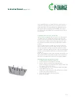
charging socket iec 62196-2 type2
•
Charging current: 16A
•
Number of poles: 3P+N+PE+PP+CP
•
Output power: 11kW
Main connection terminals
RCCB left charging socket
RCBO right charging socket
EWS-Box P
Ventilator terminals
PE terminals
Cable entry 3 x M50
Contactor right charging socket
Power supply unit
Digital meter right charging socket
Control fuse
Digital meter left charging socket
Contactor left charging socket
Clips for cable laying
Picture similar to original product
Digital meter


