13
Focus on sample surface.
For some samples, this may be as easy as bringing the focus down beyond the
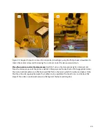
tip using the same down arrows in the Engage panel that were used to locate the tip. In the Engage
panel (Fig 9a)
, there are 2 values called “Focus Position” and “Tip Position.” The user can bring the focus
position down below the tip position by about 1 mm. If the user notices that the focus is not able to
lower, this indicates that the user has approached the 1 mm difference. Now, the user must move the
AFM head. In the Engage panel, click on “Move Tip”, and use
the arrow buttons to slowly lower the AFM
head until the sample surface comes into view and then into focus. At this location, the user may move
the stage in small increments in the x- and y-directions to locate a place to scan on the sample surface.
Using the joystick for this is not recommended. There are a few ways of making small movements using
the Video panel that are helpful at this step. In the Video panel, the user may right click on a location in
the image of the sample surface, and click on “Move
Here.” The tool will jog the stage to the indicated
location. If the user wishes to manually move the stage, there are arrow buttons on the top, bottom, left
and right edges of the video feed (Fig 9b). Again, the shift+click command on these buttons will move
the stage in the smallest possible increment in the x- and y-directions. The green crosshair used to mark
the tip location indicates to the user where the AFM tip will land during the scan. When the user is
satisfied with the location, click on the “SET” button to the right of the “Focus on Sample” button
in the
Engage panel.
The user should click on “Focus on Tip” to toggle back to the tip view
, and check that the tip is still in
focus. Then, the user should click “Focus on Surface” to toggle back to the surface view, and verify that
the surface is in focus at the correct location.
The user should verify they are in tip view before
proceeding to the next steps
.
In the Engage panel, toggle to the tip view and
click on “Move to Pre
-Engage
.”
Tune the cantilever.
Note: the user cannot tune if the camera is not in tip view. Click on Tune on the
right-hand side of the Master panel. This opens a
Cantilever tune window. Verify that the “target
amplitude” field has 1.00 V
(Fig 11)
. In this window, click on “Get Real.” This opens a menu of commonly
used probes. The user will select the type of probe that is loaded in the tool, then click on Get Real
Calibrate. This opens a new window of Thermal Fit Data (Fig 12). As the computer calibrates, this
particular window will fill in with a Gaussian peak. The user will right click on the apex of the peak, and
select “Fit Thermal Data” from the drop
-down menu that opens. Switching back to the Cantilever tune
window, the user will click on “Auto Tune”
(Fig 13). The computer calculates a resonance frequency
based on parameters from the selected probe and the thermal data. The tuning is complete when a
black trace (frequency) and teal trace (phase) appear in the window.


