55
HERU
®
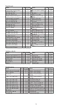
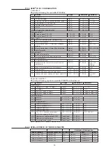
CX I/O CONFIGURATION
Controller 1:
Physical positioning for controller POL683x
IO
Function
IO type
Connection
Comments
Digitala outputs
DO1 Outside air damper
Digital
T6 (Q13,Q14)
ST1/ST2
DO2 Pump Heating, Electric heating command (stage-1)
Digital
T6 (Q23,Q24)
CP1, EHC
DO3 Pump cooling, HCP start heating
Digital
T6 (Q33,Q34)
CP2, DX-CHP
DO4 Common alarm A+B, alarm A
Digital
T6 (Q43,Q44)
DO5 Alarm B
Digital
T7 (Q53,Q54)
DO6 AUX operating mode indication
Digital
T7 (Q63,Q64)
Analogue outputs
AO1 Supply air signal 0-10 V DC
0...10 V DC
T3 (Y1,M)
TF-EC
AO2 Extract air signal 0-10 V DC
0...10 V DC
T3 (Y2,M)
FF-EC
Binary inputs
DI1
Alarm fans (common alarm Sup-ply+Extract)
Digital
T4 (D1,M)
TF-EC+FF-EC
DI2
Alarm HRW recovery
Digital
T4 (D2,M)
EMS
DI3
External control input 1 (Timer input), presence
detector
Digital
T4 (D3,M)
TM1, GN1
DI4
External control input 2, Alarm filter, Quick stop
Digital
T4 (D4,M)
TM2, GP3/GP4
DI5
Alarm fire/smoke
Digital
T4 (D5,M)
Universal inputs
X1
Supply air temperature
NI1KLG
T2 (X1,M)
GT1
X2
Extract air temperature, room temperature
NI1KLG
T2 (X2,M)
GT2, GTR
Universal inputs/outputs
X3
Outside temperature
NI1KLG
T2 (X3,M)
GT3
X4
Freeze protection sensor, Alarm electric heater/
overheating
NI1KLG
T2 (X4,M)
GT8, GT9
(GT9-A/
GT9-M)
X5
Exhaust air temperature, min limit recovery
NI1KLG
T2 (X5,M)
GT42
X6
Recovery signal
AO 0… 10 V DC
T2 (X6,M)
EMS
X7
Heating valve signal, electric heater signal
AO 0… 10 V DC
T2 (X7,M)
SV1
X8
Cooling valve signal, cooling unit signal, signal HCP
AO 0… 10 V DC
T2 (X8,M)
SV2, KM1,
HCP
Expansion module 1:
Physical positioning expansion module POL955 with address 1
IO
Function
IO type
Connection
Comments
Digital outputs
DO11 Cooling unit 1-stage, DX stage-1
Digital
T3 (Q13,Q14)
KM1, DX-1
DO12 DX stage-2
Digital
T3 (Q23,Q24)
DX-2
DO13 Indication supply air stage 2
Digital
T3 (Q33,Q34)
Supply air Stage-2 Ind
DO14 Indication supply air stage 3
Digital
T4 (Q43,Q44)
Supply air Stage-3 Ind
Analogue outputs
AO11 Back-up
0...10 V DC
T5 (Y1,M)
AO12 Back-up
0...10 V DC
T5 (Y2,M)
Universal inputs/outputs
X11
Supply air pressure (GP1)
AI 0… 10 V DC
T1 (X1,M)
GP1
X12
Extract air pressure (GP2)
AI 0… 10 V DC
T1 (X2,M)
GP2
X13
Supply air flow (GF1)
AI 0… 10 V DC
T1 (X3,M)
GF1
X14
Extract air flow (GF2)
AI 0… 10 V DC
T1 (X4,M)
GF2
X15
CO2 (GQ1), Humidity sensor room
(GM1), Ext. setp. 0-10V (TU1)
AI 0… 10 V DC
T2 (X5,M)
GQ1, GM, TU1
X16
Alarm/return Cooling pump/DX/KM
Digital Input
T2 (X6,M)
X17
Alarm/return Heating pump
Digital Input
T2 (X7,M)
X18
DI summer/winter switch
Digital Input
T2 (X8,M)
Note 1)
DX-CHP
= DX- Cooling & Heating Pump
HERU
®
ADDRESS LIST MODBUS MASTER
Description I/O designation
Type of function
Pressure sensor unit
I/O type
Pxxx
x40x
xxx1
Supply air flow, GF1
QBM68.2500
P411
Pressure
MB address 41
1=P1
Extract air flow, GF2
QBM68.2500
P421
Pressure
MB address 41
1=P1
Supply air pressure, GP1
QBM68.2525
P401
Pressure
MB address 40
1=P1
Extract air pressure, GP2
QBM68.2525
P402
Pressure
MB adress 40
2=P2
11.12
11.13
1270466_utg3_HERU_400_1200_eng.indd 55
2020-10-28 11:59:49
1270466_utg3_HERU_400_1200_eng.pdf 55
2020-10-28 12:04:21
Содержание HERU 1200 S EC
Страница 59: ...59 START PAGE MAIN INDEX UNIT 11 23...
Страница 60: ...START PAGE MAIN INDEX SYSTEM OVERVIEW 60 START PAGE MAIN INDEX CONFIGURATION 11 24 11 25...
Страница 71: ......


