47
STEP MOTOR VARIMAX
The rotor is powered by a step motor with automatic restart and alarm reset in the
event of power failure. The unit has an integrated blow-off function as standard.
When the rotor is stationary, a holding torque is activated, which ensures that the
rotor actually remains stationary.
The control unit is equipped with a rotation monitor that emits an alarm if e.g. the
belt becomes dislodged. A built-in input signal offset provides an efficiency proportio-
nal to the input signal.
Two LED lights indicate operation.
The alarm is triggered for the following reasons:
•
Rotation
monitor
•
Motor
temperature
•
Overvoltage
•
Undervoltage
• Over/under temperature, control unit
•
Short
circuit
•
Internal
fault
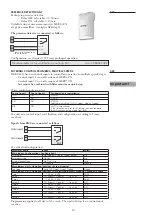
Connection diagram:
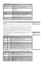
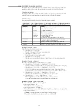
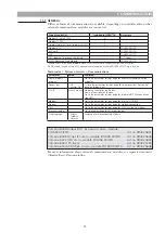
Functions:
Operation indication in the control unit:
On/alarm
“Voltage on” will glow steadily.
Flashes when the control unit has been tripped.
Operation
Illuminates when the motor will rotate, i.e. when the input signal exceeds
the threshold value
Rotation
Flashes every time the magnet passes the magnet sensor, regardless the
setting of the DIP switch “Rotation monitor”.
Also flashes if the input signal is lower than the threshold value.
11. Miscellaneous
ROTARY HEAT EXCHANGER CONTROL UNIT
11.1
DIP switches ON to the left
Operational indications
Alarm indications
Adjustments
Push buttom for Reset
1270466_utg3_HERU_400_1200_eng.indd 47
2020-10-28 11:59:48
1270466_utg3_HERU_400_1200_eng.pdf 47
2020-10-28 12:04:21
Содержание HERU 1200 S EC
Страница 59: ...59 START PAGE MAIN INDEX UNIT 11 23...
Страница 60: ...START PAGE MAIN INDEX SYSTEM OVERVIEW 60 START PAGE MAIN INDEX CONFIGURATION 11 24 11 25...
Страница 71: ......


