12
Table 6.2.
Measurement speed modes.
OSR
1
Index
ADC
mode
ADC
(samples/
data point)
ADC
2
RMS
Noise
SMU 1/2
3
(data
points/sec)
Vsense 1/2
3
(data points/
sec)
0
x1
64
23 μV
N / A
N / A
1
x1
128
3.5 μV
525
785
2
x1
256
2 μV
276
414
3
x1
512
1.4 μV
142
213
4
x1
1024
1 μV
72
108
5
x1
2048
750 nV
36
55
6
x1
4096
510 nV
18
27
7
x1
8192
375 nV
9
12
8
x1
16384
250 nV
4.5
6
9
x1
32768
200 nV
2.2
3
There is some allowance for being beyond these limits (± 10 V and ±200 mA). The unit has internal voltage
and current limits set at ±10.5 V and ±225 mA. If a voltage or current greater than these values is measured
on either SMU, the red error LED next to the SMU will turn on and the output voltage of the SMU will be set
to 0 V. This is a measure to reduce the possibility of damaging the unit due to excessive voltages or currents.
The voltage and current limits can be changed programmatically, but they should not be increased past the
default values as this will increase the possibility of damaging the unit.
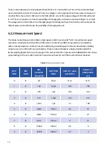
6.2.2 Measurement Speed
The Ossila Source Measure Unit utilises a high-speed, 24-bit no Latency ∆Σ™ ADC. It provides ten speed/
resolution combinations (6.9 Hz/200 nV RMS noise to 3.5 kHz/25 µV RMS noise) which can be selected,
with no latency between conversion results. Additionally, a double-speed mode can be selected, enabling
output rates up to 7 kHz with one cycle latency. These modes are linked to a single variable called OSR
(Oversampling Rate) which is used to program the unit and take the measurement.
Table 6.2
lists the various
speed settings of the unit, with maximum measurement rates for both SMU and voltmeter channels.
Содержание UNIT-X200
Страница 16: ...16 Figure7 3 TheOssilaFrontPanelPCsoftware Figure7 2 The24VDCpoweradapter ...
Страница 32: ......

