background image


enabling 

materials

 science 


ossila.com 


Dip Coater 

User Manual 

Manual Version: 1.0.0 

Product code: L2006A1 

Product Version: 1.0 

Software Version: 1.0 

Содержание Dip Coater

Страница 1: ...enabling materials science ossila com Dip Coater User Manual Manual Version 1 0 0 Product code L2006A1 Product Version 1 0 Software Version 1 0 ...

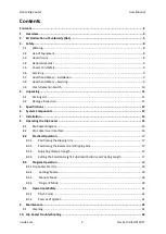
Страница 2: ...ifications 12 6 System Components 13 7 Installation 14 8 Operating the Dip Coater 15 8 1 Dip Coater Diagram 15 8 2 Dip Coater User Interface 16 8 3 Practical Operation 17 8 3 1 Positioning the Dipping Arm 17 8 3 2 Positioning the Reservoir and Dipping Arm 17 8 3 3 Adjusting Clamp Strength 17 8 3 4 Setting the Solution Height Substrate Position and Coating Length 17 8 4 Program Operation 18 8 4 1 D...

Страница 3: ...Ossila Dip Coater User Manual ossila com 3 Ossila Limited 2017 11 Ossila Contact Details 43 12 List of Related Products 44 13 Revision History 45 ...

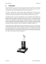
Страница 4: ...ess and properties of the deposited film Equipped with high precision motors the system offers excellent accuracy and reproducibility for travel speeds and substrate positioning In addition the system provides a wide range of coating speeds ranging from 0 01mm s 1 to 50mm s 1 variable withdrawal rates for graded films and the option to perform repeat cycles Additional software features include use...

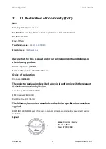
Страница 5: ...to the following product Product Dip Coater L2006A1 Serial number L2006A 1000 1000 1000 xxxx Object of declaration Dip Coater L2006A1 The object of declaration described above is in conformity with the relevant Union harmonisation legislation Low Voltage Directive 2014 35 EU EMC Directive 2014 30 EU RoHS Directive 2011 65 EU The following harmonised standards and technical specifications have been...

Страница 6: ...vornost da je navedena oprema sukladna s mjerodavnim zakonodavstvom EU a o usklađivanju koje je navedeno na prethodnoj nim stranici ama ovoga dokumenta Italiano Dichiarazione di conformità UE Produttore Ossila Ltd Solpro Business Park Windsor Street S4 7WD UK Si dichiara sotto la propria personale responsabilità che l apparecchiatura in elenco è conforme alla normativa di armonizzazione UE rilevan...

Страница 7: ...z veljavno uskladitveno zakonodajo EU navedeno na prejšnji strani prejšnjih straneh tega dokumenta Suomi EU vaatimustenmukaisuusvakuutus Valmistaja Ossila Ltd Solpro Business Park Windsor Street S4 7WD UK Vakuutamme täten olevamme yksin vastuussa siitä että tässä asiakirjassa luetellut laitteet ovat tämän asiakirjan sivuilla edellisillä sivuilla kuvattujen olennaisten yhdenmukaistamista koskevien ...

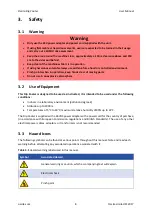
Страница 8: ...can be found at various points throughout this manual Note and read each warning before attempting any associated operations associated with it Table 3 1 Hazard warning labels used in this manual Symbol Associated Hazard General warning or caution which accompanying text will explain Electrical shock Pinch point Warning Only use the 24V power adapter and power cord supplied with the unit If using ...

Страница 9: ...to the operator 3 6 Servicing If servicing is required please return the unit to Ossila Ltd The warranty will be invalidated if Modification or service has taken place by anyone other than an Ossila engineer The Unit has been subjected to chemical damage through improper use The Unit has been operated outside the usage parameters stated in the user documentation associated with the Unit The Unit h...

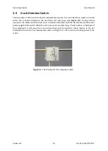
Страница 10: ... 3 1 During normal operation the safety switch will remain in a constant ON state with the bar attached to the motor pressing against the switch When the arm encounters an object e g a hand beaker or the base of the equipment it will cause the arm and the housing of the switch to rotate relative to the bar attached to the motor This releases the switch setting it to an OFF state and cutting power ...

Страница 11: ...r Dip Coating arm Power cord set specific for country of operation User guide manual 4 2 Damage Inspection Examine the components for any evidence of shipping damage If damage has occurred please contact Ossila directly for further action The shipping comes with a shock indicator to show if there has been mishandling of the package during transportation ...

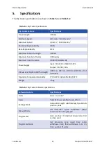
Страница 12: ...pply Input 100 230V 50 60Hz 50VA Output 24 VDC 2 0 A Dimensions Depth x Width x Height 300 mm x 200 mm x 350 mm 450 mm at full extension Operating Temperature Humidity 5 C to 40 C Up to 80 RH 31 C Weight 5 kg Table 5 2 Dip Coater Software Specifications Software Feature Specifications Units mm s 1 mm min 1 Users Total of 10 user profiles to select from Settings Mode Set solution height substrate l...

Страница 13: ...ip Coater L2006 comes with the following components Dip Coater unit Figure 6 1 Power supply cord and power supply Figure 6 2 Dipping arm and clamp Figure 6 1 The Ossila Dip Coater Figure 6 2 Main power cord and power supply The Dip Coater ships with a plug suited for the country of purchase ...

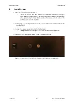
Страница 14: ...approximately 150 mm clearance above the machine to the sides of the machine and behind the machine 2 Before plugging in the Dip Coater ensure the power switch on the unit is switched to the 0 position off 3 Connect the power supply connector to the Dip Coater i See Figure 7 1 for connecting the Dip Coater to the power supply cable 4 Switch the Dip Coater power switch to the 1 position to turn on ...

Страница 15: ... Manual ossila com 15 Ossila Limited 2017 8 Operating the Dip Coater 8 1 Dip Coater Diagram An isometric view of Dip Coater is shown in Figure 8 1 with all the relevant components highlighted Figure 8 1 Dip Coater schematic ...

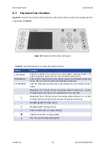
Страница 16: ...an also be altered here M MANUAL Enter Manual mode where the immersion speed and withdrawal speed can be set The arm can be immersed and withdrawn manually P PROGRAM Enter the Programming mode where saved programs can be selected and or edited Navigating up through menus increasing selected values by 1 cycling through options moving the arm upwards manual mode only Navigating down through menus de...

Страница 17: ...can be adjusted to be nearer or further away from the user by loosening the arm adjustment screw 4 Ensure that there is a distance of at least 1 cm from the edge of the baseplate of the dip coater 8 3 3 Adjusting Clamp Strength 1 Pull back one half of the clamp and insert a substrate being sure to provide support in case the clamp strength is not yet high enough 2 Let go of the substrate to check ...

Страница 18: ...1 Dip Coater Start Up 1 Switch ON position 1 the Ossila Dip Coater power switch The screen below will be shown 2 After the Ossila logo page reset the arm to the Home position by pressing the OK button While the arm is moving to the Home position the message below will be shown on the screen ...

Страница 19: ...Ossila Dip Coater User Manual ossila com 19 Ossila Limited 2017 Once the system is at the Home position the Settings Mode page will be prompted ...

Страница 20: ...the digits by pressing either the left or right button To increase or decrease the value of the selected digit press the up or down button Press OK again to exit the edit mode Note The maximum travel distance of the system is 100mm Any coating length and drying gap values refer to Step 7 should be within maximum travel distance The coating length will be auto corrected if the added value is more t...

Страница 21: ...7 3 To navigate to Substrate Position press the down button and then OK to edit the value Press the left or right button to navigate between the digits and press the up or down button to increase or decrease the selected digit Press OK again to exit the edit mode ...

Страница 22: ... between the digits and press the up or down button to increase or decrease the selected digit Press OK again to exit the edit mode Note A warning message will appear if the difference between substrate position solution height plus coating length drying gap is more than the maximum travel distance 100 mm Note A warning will appear if the substrate position is set below the solution height ...

Страница 23: ...3 Ossila Limited 2017 5 To navigate to Advanced Settings press the down button until Advanced is highlighted in yellow then press OK 6 To change the unit from mm s to mm min press OK to edit and press the left or right button to select the unit ...

Страница 24: ...ress OK again to exit the edit mode The maximum drying gap is 50 mm and the default value is 5 mm Note The default Drying Gap is 5 mm The value will reset every time the Dip Coater is switched OFF Note The maximum travel distance of the system is 100mm Any increases in coating length value in Step 2 and Drying Gap should be within this maximum travel distance The coating length will be auto correc...

Страница 25: ...Ossila Dip Coater User Manual ossila com 25 Ossila Limited 2017 8 To navigate to a previous page press the down button until Back is highlighted in yellow to select it and then press OK ...

Страница 26: ...ton on the left hand side of the screen 2 To set the immersion speed navigate to Immersion speed and press OK to edit the value To change the value press the left or right button to navigate between the digits and press the up or down button to increase or decrease the selected digit Press OK again to exit the edit mode ...

Страница 27: ...value press the left or right button to navigate between the digits and press the up or down button to increase or decrease the selected digit Press OK again to exit the edit mode 4 To operate the clamping arm press the left button to select the diagram on the screen Then press the up or down button to move the arm based on the set speed Note The maximum travel distance is 100mm ...

Страница 28: ...up and down motion Navigate to Free Motion until it is highlighted in yellow then press OK 6 To set the Free speed press OK to enter edit mode To change the value press the left or right button to navigate between the digits and press the up or down button to increase or decrease the selected digit Press OK again to exit the edit mode ...

Страница 29: ...17 7 To operate the clamping arm press the left button to select the diagram on the screen Then press the up or down button to move the arm based on the set speed 8 You can navigate to a previous page by selecting Back at the bottom of the screen and pressing OK ...

Страница 30: ...r Program Mode press the P button on the left hand side of the screen 2 To edit the program number navigate by pressing the up button then press OK to enter edit mode To change the value press the up or down button and press OK again to exit edit mode Note The maximum number of programs is 20 ...

Страница 31: ... to Cycle by pressing the down button and press OK to enter edit mode To change the value press the left or right button to navigate between the digits and press the up or down button to increase or decrease the selected digit Press OK again to exit the edit mode Note The maximum number of cycles is 1000 ...

Страница 32: ... the down button and press OK to enter edit mode To change the value press the left or right button to navigate between the digits and press the up or down button to increase or decrease the selected digit Press OK again to exit the edit mode Note The maximum Dip Speed is 50 mm s or 3000 mm min a Unit in mm s b Unit in mm min ...

Страница 33: ...ge the value press the left or right button to navigate between the digits and press the up or down button to increase or decrease the selected digit Press OK again to exit the edit mode Note The Dwell Time format is HH MM SS H Hour M Minute S Second 6 To enter the withdrawal page navigate to Withdrawal at the bottom of the screen until it is highlighted in yellow then press OK ...

Страница 34: ...own button and press the OK button to enter edit mode To change the value press the left or right button to navigate between the digits and press the up or down button to increase or decrease the selected digit Press OK again to exit the edit mode Note The maximum Initial Withdrawal Speed is 50 mm s or 3000 mm min a Unit in mm s b Unit in mm min ...

Страница 35: ...wn button and press the OK button to enter edit mode To change the value press the left or right button to navigate between the digits and press the up or down button to increase or decrease the selected digit Press OK again to exit the edit mode Note The maximum Final Withdrawal Speed is 50 mm s or 3000 mm min a Unit in mm s b Unit in mm min ...

Страница 36: ...nge the value press the left or right button to navigate between the digits and press the up or down button to increase or decrease the selected digit Press OK again to exit the edit mode Note The Dry Time format is HH MM SS H Hour M Minute S Second 10 To return to the immersion page navigate to Immersion at the bottom of the screen until it is highlighted in yellow then press OK ...

Страница 37: ... Coater User Manual ossila com 37 Ossila Limited 2017 11 Once the all the values have been set press the START button to run the program Once the coating cycle has been completed the following message will appear ...

Страница 38: ...anual ossila com 38 Ossila Limited 2017 Note A warning will appear if any of the conditions below occur a Operation has been stopped by pressing the STOP button b Immersion Dip speed not set c Withdrawal Initial speed not set ...

Страница 39: ...Ossila Dip Coater User Manual ossila com 39 Ossila Limited 2017 d Withdrawal Final speed not set e When the maximum travel distance exceeds 100mm a warning will be given ...

Страница 40: ...Ossila Dip Coater User Manual ossila com 40 Ossila Limited 2017 f Crash detected between substrate and other hard surface e g beaker or base of the case ...

Страница 41: ... near the moving parts during the running of programmes or the manual movement of the dip coater 8 5 2 Sources of Ignition Solvents can often be highly volatile with some having flash and flame points below that of room temperature To minimise the risk of fire with solutions in use users should ensure that no sources of ignition are placed close to the dip coating system In the case of any hazardo...

Страница 42: ...a for a replacement power supply adapter No obvious cause If all the above causes have been considered there may be a fault on the board Please contact Ossila for information Crash Warning The safety switch in the crash switch housing has not been returned to its ON state Ensure that the arm position is returned to its initial position and that no obstruction to the arms movement remains The safet...

Страница 43: ... Details Ossila Contact Details Technical Contact 1st Floor Northern Block Dr Jonathan Griffin Solpro Business Park j griffin ossila com Windsor Street Sheffield S4 7WB Customer Services Contact UK Rosie Morgan r morgan ossila com Phone no 44 0 114 2999 180 Fax no 44 0 800 098 8142 ...

Страница 44: ...ed ITO Substrates for OFET and Sensing ITO Coated Scale Up Substrates S281 A 25 X 75 mm unpatterned ITO glass substrate useful for custom patterning and other varied uses Quartz Coated Scale Up Substrates S261 These ultra flat glass substrates have thin 20 nm layer of synthetic quartz on the surface and are useful for control tests coating experiments and a variety of other uses Related processing...

Страница 45: ...Ossila Dip Coater User Manual ossila com 45 Ossila Limited 2017 13 Revision History Rev Date Description ...

Отзывы: