4.3. Wireless signal strength
The detector should be in the radio visibility zone of its receiver, therefore, after binding, be-
fore installation at the facility, it is strongly recommended to recognize the wireless signal strength.
To do this, turn on and place the detector and the control panel in the intended installation
locations, and then press and release the tamper button. The detector indicators display the wire-
less signal strength as follows:
LED color
Number of blinks
Signal strength
Green
3
Best
2
Good
1
Poor
Red
4
No connection
If the signal strength is poor or there is no connection, it is recommended to change the loca-
tion of the detector and repeat the above process in order to form a reliable reception map.
4.4.
Installing
To ensure high-quality operation of the detector, the next principals recommended during in-
stallation:
●
Place the detector at a height of 2.3 m;
●
Ensure the absence of both opaque and translucent obstacles (e.g. trees, bushes, glass
and mesh partitions/fences) in the detection zone;
●
Avoid getting into the detector detection area of obstacles whose temperature can
change significantly (for example, a wall heated by the sun)..
To install the detector:
1. The detector is mounted on any flat vertical surface using the special bracket;
2. Choose a place for installation, taking into account the signal strength in this place (see
section 4.3);
3. Unscrew the detector cover and remove the cover;
4. Unscrew the detector PCB (the screw located between the batteries) then pressing the
latch and remove the PCB;
5. On the detector housing (on its reverse side) there are 3 possible square mounting
points. Choose one of them – the most convenient for installation in this place. Drill a
4.2mm hole in this place to mount the bracket;
6. At the installation place, mark the points for mounting the bracket. If necessary, drill
holes at the installation surface according to the markup;
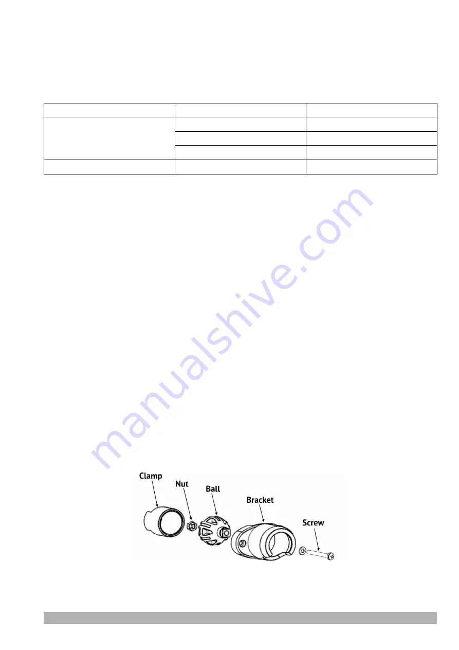
7. Assemble the bracket according to the figure below;
8. Having passed the fastening screw through the previously drilled hole in the bottom of
the housing from the inside, fix the bracket assembly to the detector body, then install
and fix the bracket at the installation place. The detector must be installed vertically
PIROUT-R
Version en_2
6


