(similar to Figure 1);
9. Install the detector PCB in the housing;
10. Insert the external antenna with the insulation-free end into the housing hole intended
for it (in its lower part) and fix it with a screw in the terminal block;
11. Close the detector cover, tighten the fixing screws;
12. Install the visor to protect against precipitation.
4.5. Adjusting
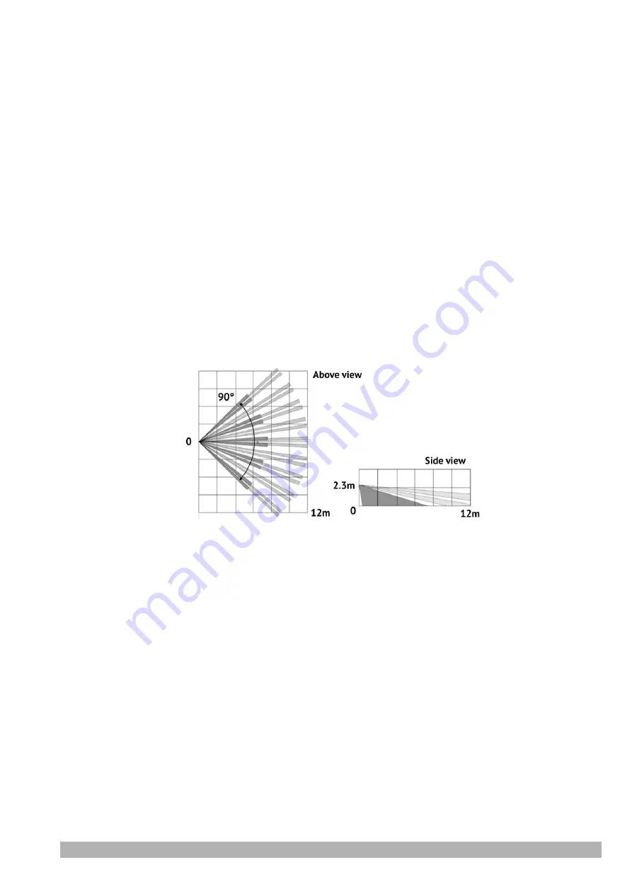
When the detector is installed, the detection zone and sensitivity of the pyrodetectors should
be adjusted.
First you must set the boundaries of the detection zone. For this:
1. Set the control panel to the armed mode and step through the detection zone. As soon as
the detector detects a violation, it sends an alarm event to the receiver in the control
panel. This event is accompanied by a red glow indicator in the first 15 minutes after
closing its cover;
2. If the actual boundaries of the detection zone do not coincide with the necessary ones,
then the detector position on the bracket should be adjusted (turn it and/or tilt to the
corresponding side). To do this, slightly loosen the screws that secure the bracket, rotate
the detector and tighten the screws again;
3. Make sure that the protected area is completely covered by the detection zone.
Figure 2. Zone detection diagram
The sensitivity of the pyrodetectors should be changed if the alarm event is generated even in
the absence of movement in the protected area. In this case, remove the
SENS HIGH
jumper. The in-
terference immunity of the detector increases at the cost of reducing the maximum detection range
to 8m.
5. Maintenance
The product work should be checked annually.
6. Operating conditions
1. Detector is designed for continuous operation.
2. Detector shall be used at the temperature of –40°С to +55°С and relative humidity of 5% to
85%.
3. If the transportation conditions differ from the operating conditions, then the detector must
be kept in the operating conditions for 2…6 hours before switching on.
PIROUT-R
Version en_2
7


