Ormandy Optimajor GLP S 3.0 Скачать руководство пользователя страница 11

Page

11 / 19

It is prohibited, under threat of warranty cancellation, to position any
device which might cut the direct communication between the safety
group and the tank. The safety device will be placed on the tank cold
water feeding duct, outside the water jacket, at a max. distance from
the tank of 1 meter.
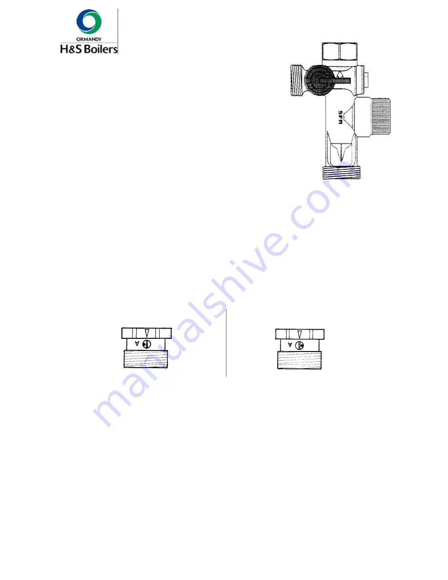
B

C

A

Cold water

(input)

Cold water (outlet)

A) Locking valve

B) Safety valve

C) Draining opening

Drainage vs. sewerage

The safety group discharge will be connected to an evacuation pipe
having a diameter at least equal to the equipment connection pipe
by means of a funnel allowing an air rate of 20 mm min.

Filling of the installation

It is important to take into account that:
-

after every tank heating, a water draining by the C ori-
fice should occur. This event can be avoided by using a
domestic water expansion pot.

-

to avoid the formation of limestone (safety group enemy)
which might deposit on the valve seat, it is required to
manually operate the safety group valve once a month, by
completing a manual discharge.

Open position to the filling

(free flow of water in both directions)

Automatic position(active valve)

Non-returnvalve

- Open the anti-thermosiphon valves (inactive/free passage).

Before filling the installation, adjust the nitrogen pressure of the expansion vessel according to the height of the installation.
You become the value of this nitrogen pressure (P

vessel

[bar]) by dividing the head of water of the installation by 10 and adding

a safety margin of 0,2 to 0,5.
Ex. : for an installation height of 6 m : P

vessel

= (6/10 + 0,3) = 0,9 bar.

When all the accessories are in place (expansion tank, security valve, manometer, ...) and that the airtightness of the
hydraulic circuits is ensured, apply the following sequence for the filling of the hot sanitary water circuit :

Z

Z

- The filling must take place slowly, the drain cocks being open or unscrewed in order to avoid to the maximum the blocking

of air.

- Verify the functioning of the automatic drain cock placed on the reheating hydraulic circuit of the tank and control the

airtightness of the connections.

- After a first filling and a first drain, the pressure to read to the manometer will be equal to the static pressure (or static

height actual of the installation) raised of 0,1 to 0,5 kg/cm² according to the cases.

- The first heating must take place at the highest possible temperature (80-90°C) and be maintained during several hours

in order to degas at maximum and the most rapidly possible.

- During this phase of heating at high temperature, the air and the released gases must be regularly evacuated by the

separation devices and of air purging.

- After a last purging, you must read the pressure to the manometer like the temperature and stop the installation (circulation

pump included); let cool up to a temperature of approximately 50°C.

- The pressure to read to the manometer average of 50°C after degasification is approximately equal to the pressure of

inflation of the vessel, raised of 0,2 to 0,5 bar. Thus the pressure with which the installation will push on the diaphragm
of the vessel will be such, that this diaphragm as this diaphragm is slightly bent and that later on no point of the installation
can never be put in depression. In the example here above, the filling pressure in cold water of the installation will have
then to be adjusted to approximately: P

FILLING

=0,9 + 0,3 = 1,2 bar.

- The filling of water in the boiler must be complete.
- Control the airtightness of all the connections and close the anti-thermosiphon valves (active).

Содержание Optimajor GLP S 3.0

Страница 1: ...Optimajor GLP S EXPORT OPTIMAJOR GLP S EXPORT 0111 00 OIL GASFIRED CENTRALHEATINGBOILER TECHNICALANDMAINTENANCEINSTRUCTIONS...

Страница 2: ...6 Spare parts 18 7 Maintenance 20 8 Guarantee conditions on Optimajor GLP S 20 Page Contents User s advices The boiler must be installed and commissioned by a registered installer in accordance with...

Страница 3: ...e calculated and carried out according to the standards in force the local obligations and the regulations of the manufacturer The hydraulic installations fuel or gases will be established according t...

Страница 4: ...48 1 84 7 60 3 101 9 72 5 119 84 7 136 2 96 6 153 3 109 2 Combustion circuit vol dm Water side losses mbar 1 7 0 9 2 7 1 4 3 9 2 5 3 2 7 6 9 3 5 8 7 4 4 Relative standby loss Water capacity l Packed...

Страница 5: ...edition of Clean Air Act 1993 should be observed To ensure safe operation of the boiler the chimney system shall be capable of the complete evacuation of the products of combustion at all times The e...

Страница 6: ...the thermal insulation and the mantle No leakage must occur during the water test Positioningthebottomrearfixingplate A onthecastiron block on the rear section Using2M8X10 DIN933 screw blocktherearpla...

Страница 7: ...ount the overall dimensions of the jacket Provide a coupling duct with a diameter of 200 mm Height of the axis of the duct 670 mm not including the base Place the chimney coupling duct Ensure the airt...

Страница 8: ...e filling of the heating circuit Verify and check the watertightness of all connections Rinse the installation by empying it Bring the pressure up to the level in accordance with the manometric height...

Страница 9: ...mp to ensure a difference of temperature between the start and return oftheboilerofminimum5 Cand ofmaximum35 C Beforeinstallingadevice itishighlysuggestedthattheinstallercheckstheconditionsofthechimne...

Страница 10: ...arenotpartofthescopeof our supply but are mentioned because requiredforagoodplantperformance If all the plant radiators are equipped with thermostatic valves a differential pressure valve should be pl...

Страница 11: ...f the hydraulic circuits is ensured apply the following sequence for the filling of the hot sanitary water circuit Z Z The fillingmust takeplace slowly the draincocksbeing openorunscrewed inorderto av...

Страница 12: ...age again Remark As far as Ecosets are concerned are the electrical connections of the circula tionpumpoftheheatingcircuitmadein the control box outisde the boiler control panel 4 3 Electricalconnecti...

Страница 13: ...ago range Climaticregulator delivered in option Lago Eco Lago E8 0634 In order to install this regulation it is necessary to interpose between the boiler connector block and the regulator a connection...

Страница 14: ...plug of connector A 4 Connect the 10 poles white connector on the connector block II of the regulator 5 Connect directly the following probes on the connector block I of the regulator AFS external pr...

Страница 15: ...P 12 poles plug of connector A 4 Connect the 10 poles white connector on the connector block II of the regulator 5 Connect directly the following probes on the connector block I of the regulator KFS b...

Страница 16: ...cuit USING LIGHTING put the boiler under tension via the main switch set the boiler thermostat at the desired temperature after a temperature setting of the installation make again a general purging a...

Страница 17: ...Page 17 19 6 Spare parts list Boiler Cast ironblock 20 21 26 12 11 10 13 14 15 16 17 19 18 23 24 25 22 32 37 36 38 30 34 33 31 32 31 35...

Страница 18: ...7 0 1 80 600 80940 22 4 M16 x 1060 tie bar n 8 0 1 80 600 81060 23 1 Reducing plug 1 1 4 3 4 1 60 110 10061 24 4 Plug 1 1 4 with square hole fig 596 1 60 100 30010 25 2 Eye bolt 1 80 121 10063 26 acc...

Страница 19: ...uted airincludingcorrosiveelementssuch as chlorine fluorine sulphur etc The use of water which is found to be unsuitable would also invalidate our guarantee 2 Our guarantee specified below commences o...

Отзывы: