


3-18
Sun Blade X6275 Server Module Service Manual • September 2013
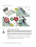
3.3.1
Identifying a Faulty Processor
1. Prepare the server module for service.
a. Power off both server module compute nodes.
See
Section 2.4, “Powering Off the Server Module” on page 2-4
.
b. Remove the server module from the Sun Blade chassis. Place it on a flat
surface.
See
Section 2.5, “Removing the Server Module From the Sun Blade Chassis” on
page 2-7
.
c. Attach an antistatic wrist strap.
See
Section 2.6, “Performing Electrostatic Discharge and Antistatic Prevention
Measures” on page 2-9
.
d. Remove the server module top cover.
See
Section 2.7, “Removing the Server Module Top Cover” on page 2-11
.
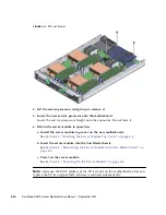
2. Press the Remind button on the motherboard. See
FIGURE 3-10
.
Note –
Do not hold the Fault Remind button down longer than necessary.
A lit green charge status LED, located next to the Fault Remind button, indicates that
the fault remind LED circuit is operational. If the charge status LED is out, the fault
remind LEDs can not function. The charge status LED indicates the test circuit power
level. After the server module is inserted into the Sun Blade chassis, the test circuit
will recharge. However, the processor error(s) must re-occur to be stored and visible
on a fault LED during the next fault remind test.
A failed processor is identified by a lit processor fault LED. See
FIGURE 3-10
.
3. Identify which processor and heat sink you are replacing.
The numbering of the processors and corresponding processor fault LEDs on the
motherboard are shown in
FIGURE 3-10
.
If the LED is...
Then the processor is...
Off
Operating properly.
On (amber)
Faulty and should be replaced.
Содержание Sun Blade X6275
Страница 1: ...Sun Blade X6275 Server Module Service Manual Part No Part No 820 6849 16 September 2013 Rev A ...
Страница 26: ...1 16 Sun Blade X6275 Server Module Service Manual September 2013 ...
Страница 47: ...Chapter 3 Servicing Server Module Components 3 7 FIGURE 3 3 DIMM Numbering and Position ...
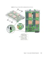
Страница 54: ...3 14 Sun Blade X6275 Server Module Service Manual September 2013 FIGURE 3 7 Replacing Flash Modules ...
Страница 59: ...Chapter 3 Servicing Server Module Components 3 19 FIGURE 3 10 Processor Fault LEDs and Remind Button Locations ...
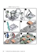
Страница 61: ...Chapter 3 Servicing Server Module Components 3 21 FIGURE 3 11 Removing a Processor ...
Страница 64: ...3 24 Sun Blade X6275 Server Module Service Manual September 2013 FIGURE 3 12 Replacing a Processor ...
Страница 72: ...3 32 Sun Blade X6275 Server Module Service Manual September 2013 FIGURE 3 14 Removing the RTC Batteries ...
Страница 80: ...3 40 Sun Blade X6275 Server Module Service Manual September 2013 ...
Страница 86: ...4 6 Sun Blade X6275 Server Module Service Manual September 2013 ...
Страница 90: ...A 4 Sun Blade X6275 Server Module Service Manual September 2013 FIGURE A 1 BIOS Utility Menu Tree ...
Страница 107: ...Appendix A BIOS Screens A 21 FIGURE A 29 BIOS Setup Utility Chipset FIGURE A 30 BIOS Setup Utility Chipset CPU Bridge ...
Страница 112: ...A 26 Sun Blade X6275 Server Module Service Manual September 2013 ...
Страница 116: ...Index 4 Sun Blade X6275 Server Module Service Manual September 2013 ...


