


2-12
Sun Blade X6275 Server Module Service Manual • September 2013
2.8
Using the Multi-Port Dongle Cable
Your chassis might ship with a multi-port dongle cable and a DB9 to RJ-45 serial
adapter cable. You can use the multi-port cable to plug devices directly into the front
of the server module for service, maintenance, and OS installation.
The multi-port cable provides connections for a VGA monitor, two USB devices, and
a serial device.
Caution –
Possible damage to the cable, server module, or chassis. Disconnect the
multi-port dongle cable when you are finished using the cable. Otherwise, the cable,
server module, or chassis can be damaged when the chassis door is closed or the
cable is abruptly pulled.
2.8.1
Connecting the DB9 to RJ-45 Serial Adapter Cable
The DB9 to RJ-45 serial adapter cable provides DB9 serial access to the server module
through an RJ-45 connection.
Your multi-port dongle cable might have three cables or four cables. If your
multi-port cable has three cables, connect to the serial port using the RJ-45 connector.
If your multi-port cable has four cables, connect to the serial port using the DB9
connector, and do
not
use the RJ-45 connector. Use the DB9 to RJ-45 adapter cable, if
necessary.
2.8.2
Attaching a Multi-Port Dongle Cable
1. Insert the multi-port dongle cable into the universal connector port (UCP) on
the server module front panel. See
FIGURE 2-6
.
2. Connect the multi-port dongle cable connections as appropriate.
Содержание Sun Blade X6275
Страница 1: ...Sun Blade X6275 Server Module Service Manual Part No Part No 820 6849 16 September 2013 Rev A ...
Страница 26: ...1 16 Sun Blade X6275 Server Module Service Manual September 2013 ...
Страница 47: ...Chapter 3 Servicing Server Module Components 3 7 FIGURE 3 3 DIMM Numbering and Position ...
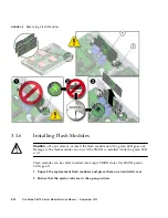
Страница 54: ...3 14 Sun Blade X6275 Server Module Service Manual September 2013 FIGURE 3 7 Replacing Flash Modules ...
Страница 59: ...Chapter 3 Servicing Server Module Components 3 19 FIGURE 3 10 Processor Fault LEDs and Remind Button Locations ...
Страница 61: ...Chapter 3 Servicing Server Module Components 3 21 FIGURE 3 11 Removing a Processor ...
Страница 64: ...3 24 Sun Blade X6275 Server Module Service Manual September 2013 FIGURE 3 12 Replacing a Processor ...
Страница 72: ...3 32 Sun Blade X6275 Server Module Service Manual September 2013 FIGURE 3 14 Removing the RTC Batteries ...
Страница 80: ...3 40 Sun Blade X6275 Server Module Service Manual September 2013 ...
Страница 86: ...4 6 Sun Blade X6275 Server Module Service Manual September 2013 ...
Страница 90: ...A 4 Sun Blade X6275 Server Module Service Manual September 2013 FIGURE A 1 BIOS Utility Menu Tree ...
Страница 107: ...Appendix A BIOS Screens A 21 FIGURE A 29 BIOS Setup Utility Chipset FIGURE A 30 BIOS Setup Utility Chipset CPU Bridge ...
Страница 112: ...A 26 Sun Blade X6275 Server Module Service Manual September 2013 ...
Страница 116: ...Index 4 Sun Blade X6275 Server Module Service Manual September 2013 ...


