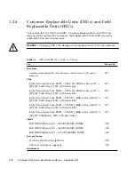


2-8
Sun Blade X6275 Server Module Service Manual • September 2013
Caution –
Damage to system components can occur through improper handling.
Observe the proper ESD precautions when handling the server module. Wear a
securely grounded ESD wrist strap. Handle components by the edges only. Do not
touch metal contacts.
Caution –
Do not reinsert
a server module until at least 20 seconds has elapsed since
the server module was disengaged from the midplane connector.
Caution –
Server modules should only be removed if the blue LED is lit, or if you are
certain that a firmware update is not in progress. Pulling the server module out of the
chassis during a firmware update might damage the server module, which might not be
repairable in the field.
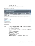
To remove the server module from the Sun Blade 6048 or Sun Blade 6000 chassis.
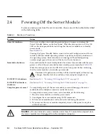
1. Power off both server module compute nodes or place them in standby power
mode.
See
Section 2.4, “Powering Off the Server Module” on page 2-4
for more
information.
When the server module compute nodes are in standby power mode, the OK
LEDs blink (0.1 second on, 2.9 seconds off) on the front panel.
2. Squeeze and hold green ejector buttons. See
FIGURE 2-4
.
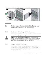
3. Open the ejector levers by rotating both ejector arms away from the server
module at the same time, to unseat the server module from the Sun Blade
chassis connector.
4. Pull the server module out of the Sun Blade chassis by the ejector levers until
you are able to grasp the server module with both hands to pull it out of the
Sun Blade chassis.
5. Insert a server module filler panel into the empty slot, if the Sun Blade chassis
is powered on.
Caution –
Do not operate the system with empty slots. Always insert a server
module filler panel into an empty slot within 60 seconds to reduce the possibility of
server module shutdown.
6. Set the server module on an antistatic surface. See the next section.
Содержание Sun Blade X6275
Страница 1: ...Sun Blade X6275 Server Module Service Manual Part No Part No 820 6849 16 September 2013 Rev A ...
Страница 26: ...1 16 Sun Blade X6275 Server Module Service Manual September 2013 ...
Страница 47: ...Chapter 3 Servicing Server Module Components 3 7 FIGURE 3 3 DIMM Numbering and Position ...
Страница 54: ...3 14 Sun Blade X6275 Server Module Service Manual September 2013 FIGURE 3 7 Replacing Flash Modules ...
Страница 59: ...Chapter 3 Servicing Server Module Components 3 19 FIGURE 3 10 Processor Fault LEDs and Remind Button Locations ...
Страница 61: ...Chapter 3 Servicing Server Module Components 3 21 FIGURE 3 11 Removing a Processor ...
Страница 64: ...3 24 Sun Blade X6275 Server Module Service Manual September 2013 FIGURE 3 12 Replacing a Processor ...
Страница 72: ...3 32 Sun Blade X6275 Server Module Service Manual September 2013 FIGURE 3 14 Removing the RTC Batteries ...
Страница 80: ...3 40 Sun Blade X6275 Server Module Service Manual September 2013 ...
Страница 86: ...4 6 Sun Blade X6275 Server Module Service Manual September 2013 ...
Страница 90: ...A 4 Sun Blade X6275 Server Module Service Manual September 2013 FIGURE A 1 BIOS Utility Menu Tree ...
Страница 107: ...Appendix A BIOS Screens A 21 FIGURE A 29 BIOS Setup Utility Chipset FIGURE A 30 BIOS Setup Utility Chipset CPU Bridge ...
Страница 112: ...A 26 Sun Blade X6275 Server Module Service Manual September 2013 ...
Страница 116: ...Index 4 Sun Blade X6275 Server Module Service Manual September 2013 ...


