Electrical Installation
67
-
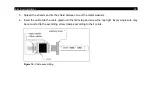
1. To install an interface, plug the interface board into the place provided, which is located beside the
display. In the correct position the holes of the interface match with the thread holes of the electronic
box.
2. Press the board down to connect it and use both M3x5 screws for fixing. Plug the preassembled
interface cable with the terminal block into the male connector of the interface board.
4.7.3
Relay outputs
The switching thresholds are in accordance with the values for alarm 1 and 2
. The alarm values are set according to the
. For
advanced settings (change of low- and high alarm) a digital interface (USB, RS232) and the
software CompactConnect is needed.
A simultaneous installation of a digital interface and the relay outputs is not possible.
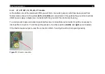
The CTlaser can optionally be equipped with a relay output. The relay board will be installed in the same way
as the digital interfaces.
The relay board provides two fully isolated switches, which have the capability to switch
max 60 VDC/ 42 VAC
RMS
, 0.4 A, DC/AC. A red LED shows the closed switch.
Содержание CTlaser 05M
Страница 1: ...Operator s Manual optris CTlaser LT LTF 05M 1M 2M 3M MT F2 F6 G5 P7 Infrared thermometer...
Страница 8: ...8 Appendix C Smart Averaging 96 Appendix D Declaration of Conformity 97...
Страница 44: ...44 Figure 2 Mounting bracket adjustable in one axis Order No ACCTLFB standard scope of supply...
Страница 45: ...Mechanical Installation 45 Figure 3 Electronic box...
Страница 97: ...Appendix D Declaration of Conformity 97 Appendix D Declaration of Conformity...
Страница 98: ...optris CTlaser E2018 12 A...


