background image

4.5. Using the software

CAUTION!

 Do not switch the laser ON if the device is not 

adjusted  properly,  it  may  damage  or  destroy  optical 
elements. 

Launch LPA program using LPA icon on the desktop. 


4.5.1. Connection, device selector

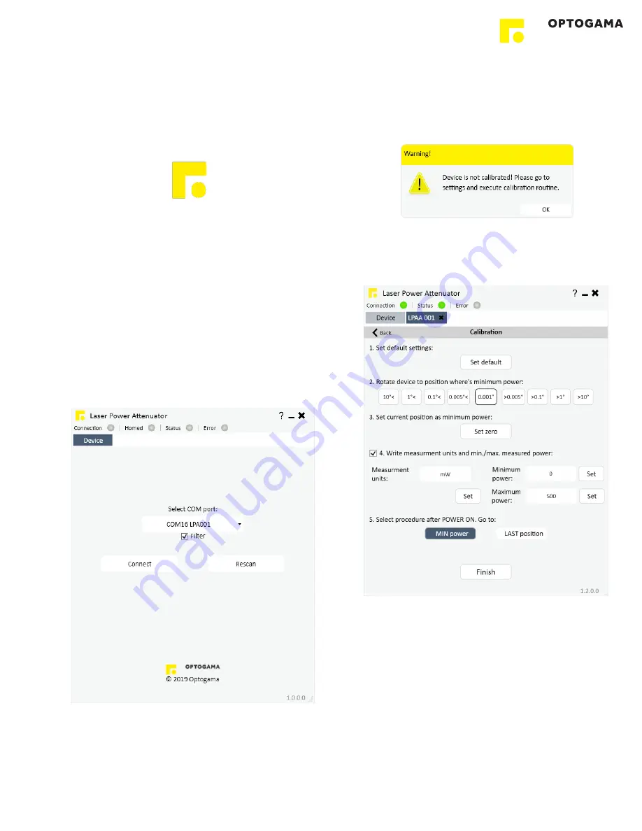
10. Device selector window will appear. Select COM port (to 

which  the  laser  power  attenuator  is  connected)  from  the 
drop  down  menu.  Press  “

Connect

”  to  connect  the 

device or “

Rescan

” if your device is not visible.  

Select “

Filter

” when device is connected via USB cable. 

All other COM ports will be hidden except our device.  
 

NOTE: 

When  connecting  via  RS232  cable  “Filter”  must 

be deselected, otherwise device will not be visible. 


4.5.2. Settings, calibration

11.  Using  laser  power  attenuator  for  the  first  time  the 

calibration  is  required.  The  information  window  will 
appear: 


12.  For LPA-A calibration, move your mouse to the left side 

of  the  window  on  a  gear  symbol  from  the  sliding  menu 
and select “Settings”. Settings menu will appear: 


13.  To succeed calibration please follow calibration steps: 

1. Set default settings. 

2. Find minimum laser power position. 

3. Set current position as minimum power “Set zero”. 

4. Choose additional measurement units if necessary 

5. Select  procedure  after  turning  the  device  ON.  By 

default the device will reach last desired value 

6. Calibration  is  done  and  device  is  ready  to  use. 

Press  “Finish”  and  you  will  be  greeted  into  MAIN 
window.  

LPA

10

Содержание LPA-A v2 Series

Страница 1: ...MANUAL v2 2 LPA A ADVANCED and INTEGRATED MOTORISED LASER POWER ATTENUATOR LPA A v2 series KEY for DISCOVERIES ...

Страница 2: ...ller 7 3 5 1 Interfaces pinout 7 3 6 Voltage levels 7 3 7 What s in the box 7 3 8 Available accessories 7 4 Software 8 4 1 Minimum Hardware requirements recommended 8 4 2 System requirements 8 4 3 Supported client operating systems 8 4 4 Installing the software 8 4 5 Using the software 10 4 5 1 Connection device selector 10 4 5 2 Settings calibration 10 4 5 3 Main window 11 4 6 Updating the firmwa...

Страница 3: ... result in damage to the device components connected to it or operator NOTE Sections marked with this symbol indicate important information on laser power attenuator or about this manual Due to constant development of our products we reserve the right to make changes in the production line without further notice Up to date information is available at our website www optogama com If there are any f...

Страница 4: ...ice is installed correctly and well adjusted and all cover stickers are removed Protective measures should be considered if necessary Electrical safety requirements must be complied while operating this device CAUTION High laser output power may damage or destroy optical elements CAUTION The device is meant to be used with a collimated beam Users take full responsibility when using the device with...

Страница 5: ...le α should be adjusted to improve device contrast 2 deg maximum Use HEX 1 5 key Clock wise to decrease angle Counter clock wise to increase angle Fig 2 Schematic explanation of optical design of laser power attenuator LPA A 2 2 Features and advantages Integrated controller Absolute position encoder no homing required High accuracy 0 005 deg less than 0 01 of laser power Resolution 0 002 deg 7 2 a...

Страница 6: ...tions 3 2 Mechanical specifications 3 3 Electronic specifications 3 4 Conditions Clear input aperture ø15 mm Clear output aperture ø15 mm Power attenuation range 0 1 to 98 LIDT coating 10 J cm2 10 ns 1064 nm Adjustment time 0 2 sec min to max Aboslute pos encoder Yes Resolution 175 542 µsteps in full rotation 0 002 deg 7 2 arcsec 0 035 mrad Accuracy 0 005 deg 18 arcsec 0 087 mrad less than 0 01 Mo...

Страница 7: ...f up to 15 V Because the voltage levels are higher than logic levels typically used by integrated circuits special intervening driver circuits are required to translate logic levels These also protect the device s internal circuitry from short circuits or transients that may appear on the RS 232 interface and provide sufficient current to comply with the slew rate requirements for data transmissio...

Страница 8: ... Vista SP2 Windows 7 SP1 Windows 8 Windows 8 1 NET included with OS Windows 10 NET 4 6 included with OS Windows Server 2008 SP2 R2 Windows Server 2012 NET included with OS 4 4 Installing the software 1 Check and download the latest LPA software from our website www optogama com www 4lasers com or contact us directly at sales optogama com 2 Run the downloaded software installation file Installation...

Страница 9: ...the device and controller via HD 15 cable 6 Connect the PC and controller via USB or RS232 cable 7 Plug in power supply to controller and AC adaptor to wall outlet 8 The device will be detected and configured 9 The device installation is complete 9 ...

Страница 10: ...st be deselected otherwise device will not be visible 4 5 2 Settings calibration 11 Using laser power attenuator for the first time the calibration is required The information window will appear 12 For LPA A calibration move your mouse to the left side of the window on a gear symbol from the sliding menu and select Settings Settings menu will appear 13 To succeed calibration please follow calibrat...

Страница 11: ... Emergency zero If active the attenuator will instantly go to minimum position 0 Desired power value in your desired units Enter required power value Press Enter To enable go to settings Connection Green device is connected Status Green blinking in motion Green target is reached Error Red indicates and error Drag cursor here to obtain error Reconnect Select this icon to reconnect the device if it ...

Страница 12: ...atible software had been delivered with device In order to update your device or rewrite device firmware USB cable must be used update through RS232 cable is not available 1 Click button Firmware Upgrader in the About tab of LPA software 2 In the opened window press Update button You will be asked if you really want to update device After a warning device motors will be shut down and update will s...

Страница 13: ...PA PWR _X XXX Command used to set a new power value in percentages LPA PWR _10 LPA PWR_10 000 LPA PWR _45 1 LPA PWR_45 100 LPA PWR _0 07 LPA PWR_0 070 LPA ANG LPA ANG_X XXX Command used to get the current angle value in degrees Read from absolute encoder 0 360 deg LPA ANG LPA ANG_22 143 LPA ANG _X XXX LPA ANG_X XXX Command used to set the angle value in degrees 0 360 LPA ANG _22 5 LPA ANG_22 500 L...

Страница 14: ...13 bit14 bit15 device calibration is done LPA STATUS LPA 1_0 LPA STATUS LPA 0_0 LPA STATUS LPA 1_2 LPA WL LPA WL_XXX Command used to get the design wavelength LPA WL LPA WL_355 LPA FW LPA _Firmware version Command used to get firmware version LPA FW LPA _1 0 0 1 LPA ID LPA _LPAAXXXXXX Command used to get serial number LPA ID LPA _LPAA190001 Other Echo Reset Motor ON OFF LPA ECHO LPA ECHO Command u...

Страница 15: ...4 3 Serial communication example in Python 15 ...

Страница 16: ...5 Technical drawings 16 ...

Страница 17: ...17 ...

Страница 18: ...OPTOGAMA UAB Mokslininku str 2A LT 08412 Vilnius Lithuania 37052194884 sales optogama com www optogama com ...

Отзывы: