AC7A/B User’s Guide
25
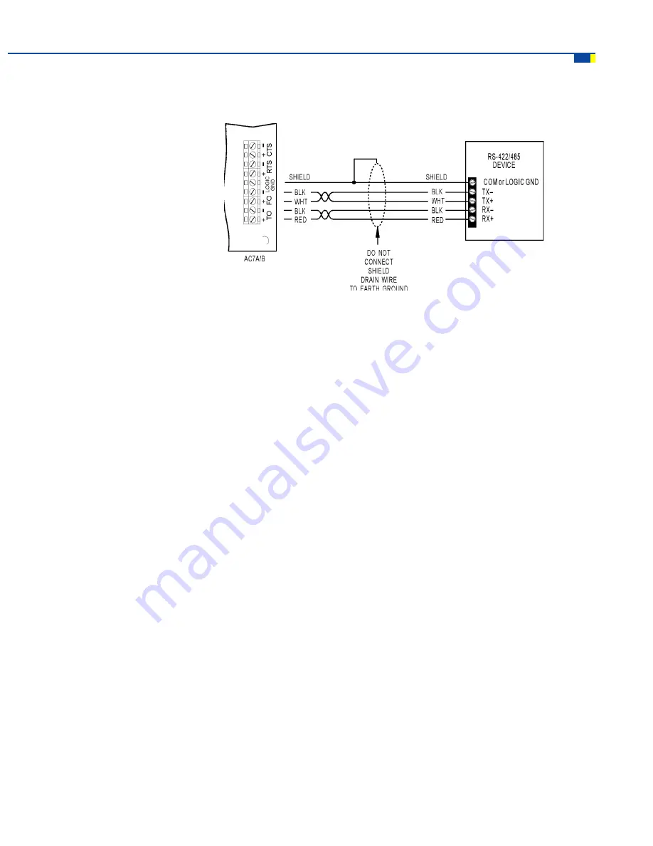
Figure 3-14: RS-422/485 Cabling Diagram (alternative, less noise immune)
General guidelines for using an AC7A/B with other RS-422/485 devices:
a.
The RS-422/485 screw terminals on the AC7A/B are labeled TO+, TO-, FO+, and FO- . This labeling
convention is for Opto 22’s Optomux I/O. For use with devices other than Opto 22’s Optomux I/O,
the following convention applies to the RS-485 port of the AC7A/B
TO+ = T
FO+ =
TO- = Transmit-
FO- = Receive-
b.
The RTS and CTS terminals are used for hardware handshaking (flow control). RTS± are outputs from the
AC7A/B. CTS± are inputs into the AC7A/B.
c.
The AC7A/B was designed to communicate in 4-wire RS-422/485 mode. In the 4-wire mode uses two
twisted-pairs of wiring (four conductors total) are used for communication. In 4-wire mode, one twisted-
pair of wires is used for the transmit signal and the other twisted pair of wires is used for the receive
signal. One additional pair (pair #3) of wires is used to connect the LOGIC GND of the AC7A/B to the
COM terminal of the RS-422/485 device.
d.
In most applications, the AC7A/B can also be used in 2-wire RS-485 mode. In the 2-wire mode uses one
twisted-pair of wiring (two conductors total) is used for communication. In 2-wire mode, the same twisted-
pair of wires is used for the transmit signal and the receive signal. One additional pair (pair #2) of wires is
used to connect the LOGIC GND of the AC7A/B to the COM terminal of the RS-485 device. To use the
AC7A/B in two wire mode, see the section titled Two-Wire RS-485 Mode (page 2
8
).
INSTALLATION (cont.)


