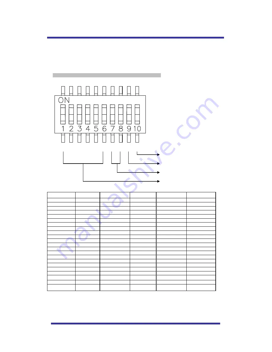
background image


25 

A-1. DIP SW SETTING 

Mini  Speed  Dome  camera  provides  up  to  63  cameras  ID  and  it

’s  an  adjustable  ID  with  1

st

~6

th

  of  Dip 

switch.   

Open the camera case to set ID using DIP SW1. 

      * Factory default: Camera ID = 1, PELCO-D Baud Rate: 2400bps 


A-2. ID SETTING 

(1-ON, 0-OFF) (1

10) 

DIP SW 

ID VALUE 

DIP SW 

ID VALUE 

DIP SW 

ID VALUE 

100000XXXX


111010XXXX


23 

101101XXXX


45 

010000XXXX


000110XXXX


24 

011101XXXX


46 

110000XXXX


100110XXXX


25 

111101XXXX


47 

001000XXXX


010110XXXX


26 

100011XXXX


48 

101000XXXX


110110XXXX


27 

100011XXXX


49 

011000XXXX


001110XXXX


28 

010011XXXX


50 

111000XXXX


101110XXXX


29 

110011XXXX


51 

000100XXXX


011110XXXX


30 

001011XXXX


52 

100100XXXX


111110XXXX


31 

101011XXXX


53 

010100XXXX


10 

000001XXXX


32 

011011XXXX


54 

110100XXXX


11 

100001XXXX


33 

111011XXXX


55 

001100XXXX


12 

010001XXXX


34 

000111XXXX


56 

101100XXXX


13 

110001XXXX


35 

100111XXXX


57 

011100XXXX


14 

001001XXXX


36 

010111XXXX


58 

111100XXXX


15 

101001XXXX


37 

110111XXXX


59 

000010XXXX


16 

011001XXXX


38 

001111XXXX


60 

100010XXXX


17 

111001XXXX


39 

101111XXXX


61 

010010XXXX


18 

000101XXXX


40 

011111XXXX


62 

110010XXXX


19 

100101XXXX


41 

111111XXXX


63 

001010XXXX


20 

010101XXXX


42 


101010XXXX


21 

110101XXXX


43 


011010XXXX


22 

001101XXXX


44 


DIP SWITCH SETTING


Termination 

Protocol 

ID Set 

Baud rate 

Содержание Mini Speed Dome Camera

Страница 1: ...Rev 1 01 dated on Dec 04 2006 10X Mini Speed Dome Camera Instruction Manual MINI SPEED DOME CAMERA ...

Страница 2: ...erating Keys Diagnostic OSD Menu Setting A OSD Menu Table B DOME SET C CAMERA SET D PRESET E AUTO SCAN F TOUR SET G PRIVACY SET H PATTERN SET I ALARM SET J SECTOR SET DIP Switch Setting A ID Setting DIP SW1 B Protocol Baud Rate Setting DIP SW1 9 10 Trouble Shooting Specification Dimension CONTENTS 3 3 4 5 6 7 8 9 10 11 16 18 19 20 21 22 23 24 25 26 27 28 29 ...

Страница 3: ...nstall the product in extreme high or low temperature Never drop hit strongly nor vibrate the product Never expose the product to direct sunlight or severe ray Never touch the front glass of the product Never install the product in areas exposed to rain or water What s in the Box This symbol is intended to alert the user to the presence of un insulated dangerous voltage within the product s enclos...

Страница 4: ...tion to big shop shopping center airport highway and so on Quick Operation Keys This camera provides quick functional keys in other to be easily controlled by any other controller or DVR Various Surveillance Functions Auto Scan repeats pan and tilt between two preset positions with different speed and dwell time 8 Group Tour up to 8 Programmable Group tours available and each group is consisting u...

Страница 5: ...5 NAMES OF EACH PART 1 Surface Mount Adaptor 2 Cap Screw PT3 4 2EA 3 Dip Switch 4 Terminal Block 5 Main body ...

Страница 6: ...ase and separate dome cover from the main base Screws won t be removed 3 Connect power DC12V 1 5 A to Power and GND 4 Connect video to Video and GND 5 Connect communication cable to RS 485 connectors 6 Connect alarm cable to GND like 1 and GND 2 and GND 3 and GND 4 and GND You can use both N O N C methods Don t screw too tightly It can be the cause of defect INSTALLATION ...

Страница 7: ...OUNT TYPE 1 Fix the surface mount adaptor with 4pcs of screws on the place where you want to install FIG 4 2 When you use pipe please note the standard size of pipe FIG 5 3 You can re assemble the domes INSTALLATION ...

Страница 8: ... N MODE Selectable Day Night Mode Auto Day Night Mode 95 Preset OSD MAIN MENU To enter OSD Main Menu 96 Preset FOCUS ADJUST Focus adjusting 97 Preset ALARM Selectable Enable Disable all Alarms Quick Operation Keys Table 2 Use these function keys if controller has these keys 65 preset Status Report is displayed if user wants to remove this screen press Focus Near button 92 preset This feature is po...

Страница 9: ...d after TX CONNECTION TEST If No Tested is displayed on the monitor Camera did not receive the any signal Camera did receive the signal but not correct it User should check protocol baud rate and RS 485 connection D Camera Comm Test Communication test with the camera is automatically checked OK should be displayed in these four tests before installation If all the above Tests are OK NOW EEPROM CHE...

Страница 10: ...EXIT EXIT SECTOR SET SECTOR NO 01 SECTOR ID SECTOR01 SECTOR START XXX X XX X SECTOR END XXX X XX X SAVE EXIT PATTERN SET PATT NO 01 PATT TITLE PATTERN01 DATA FILL 100 SAVE EXIT ALARM SET ALARM NO 01 ALARM INPUT OFF ALARM ACT 01 SAVE EXIT PRIVACY SET PRIVACY NO 01 DISPLAY ACTION SAVE EXIT TOUR SET TOUR NO 01 TOUR TITLE TOUR01 TOUR STEP 01 PRESET NO 01 DWELL TIME 10 SPEED 200 S SAVE AND EXIT EXIT NE...

Страница 11: ...racters using Joystick to the left or right Press ZOOM TELE button to move to the next character from left to right direction and ZOOM WIDE button to move to the next character from right to left direction Space displays when appears DEFAULT SETTING MAIN MENU DOME SETUP CAMERA SET AUTO SCAN TOUR PRAVACY PATTERN ALARM SECTOR EXIT DOME SET CAMERA ID CAM1 RECOVER OFF MANUAL SPEED 100 S AUTO FLIP OFF ...

Страница 12: ... the right direction for selecting FAST or SLOW The default setting is FAST B 6 DOME SET ALARM All alarms are available after set as ENABLE Mode Move joystick to right or left direction for selecting ENABLE DISABLE The default setting is DISABLE This function can be recalled by pushing 97 preset button B 7 DOME SET LANGUAGE Multiple languages are selectable here including English Italian and Polis...

Страница 13: ...d the menu will return to the previous page automatically if user failed 3 times After set a Password the operator must press memorized password in order to enter OSD MAIN MENU or to change the data which is memorized originally The operator must remember the password for the operation and manufacturer provides not memorized password B 8 3 DOME SET NEXT PAGE OSD DISPLAY OSD ID displayed after set ...

Страница 14: ...US B 8 5 DOME SET NEXT PAGE INITIALIZATION To clear all memorized data for tour preset sector privacy or pattern move joystick to the right direction when the cursor is on INITIALIZATION OSD DISPLAY CAMERA ID OFF PRESET ID OFF SECTOR ID OFF COORDINATE ON PREVIOUS PAGE DEFAULT SETTING SYSTEM STATUS PROTOCOL PELCO D P BAUD RATE 2400 BPS FIRMWARE VER 1 05 UPGRADED DATE 06 12 04 CAMERA MODULE SDM100 P...

Страница 15: ...tion when cursor is at LOAD OPTIMIZED DEFAULT to enter the above page Move joystick to the right or left direction in order to select YES press FOCUS NEAR button Then ALL DATA INITIALIZING is displayed about 5 7 seconds and then the menu are returned to the previous page automatically B 9 DOME SET NEXT PAGE SAVE AND EXIT To saving the memorized data and escape this page move joystick to the right ...

Страница 16: ...t seeting is 10 the aperture level is from 01 15 C 4 CAMERA SET D ZOOM Move joystick to the right direction in order to set as ON if Digital Zoom is necessary at install field The default setting is OFF C 5 CAMERA SET WB MODE White balance functions have 4 modes according to the condition of exterior lighting The default setting is AWB and it may change the mode option accoding to the lighting con...

Страница 17: ...sation is activated This function can be recalled by pushing 93 preset button C 8 CAMERA SET D N MODE ICR filter is changeable according to the lighting AUTO NIGHT MODE DAY MODE The default setting is AUTO MODE This function can be recalled by pushing 94 preset button C 9 CAMERA SET DSS MODE DIGITAL SLOW SHUTTER If DSS turns on digital slow shutter is working Per second the electronic shutter will...

Страница 18: ...racter from the right to left direction Space displays when appears D 3 PRESET PAN XXX X TILT XX X Press FOCUS FAR button in order to set preset position then use the joystick to the position where memorized preset no is needed Then press FOCUS FAR button again after setting a preset location D 4 PRESET SAVE Move joystick to the right direction when the cursor is at SAVE and then the cursor will b...

Страница 19: ...TO SCAN ENDLESS Auto Scan can use endless rotation move joystick to the right direction in order to select ON Otherwise the default setting is OFF E 5 AUTO SCAN SPEED User can use auto scan speed from 05 S up to 35 S and the default setting is 10 S E 6 AUTO SCAN DWELL TIME To select dwell time move joystick to the left or right direction in order to adjust dwell time Possible to set from 01 second...

Страница 20: ...ts of up to 60 preset steps with different dwell time and speed It is possible to match any preset for each tour step F 4 TOUR SET PRESET NO The decided tour step 1 64 it is possible to select any preset no up to 64 The default setting is BLK F 5 TOUR SET DWELL TIME Dwell time provides up to 99 seconds from 01 second The default setting is 03 seconds F 6 TOUR SET SPEED Each tour step can be set wi...

Страница 21: ...n when the cursor is on ACTION After changed to ADJUST MODE press FOCUS FAR button in order to adjust the size of blocking area The size of blocking area can be adjustable by using joystick up down or left right After adjusting size of blocking area press FOCUS FAR button to escape ADJUST mode ADJUST You can change the masking size by using joystick to the left or right direction MOVE You can move...

Страница 22: ...to left direction Space displays when appears Pattern title is not displayed on the monitor but only for the reference of user H 3 PATTERN SET DATA FILL To fill the programming data press FOCUS FAR button in order to start the data fill up Filling data is programmed according to the joystick movement Press FOCUS FAR button again in order to escape H 4 PATTERN SET SAVE To saving the filling data mo...

Страница 23: ...r up to 165 Group tour up to 8 Pattern up to 8 Move joystick to the right or left direction to select any preset number group tour no or pattern no I 4 ALARM SET SAVE After setting the alarm input ways and activation to save the data move joystick to the right direction when the cursor is on SAVE After saving the data the cursor moves to Alarm NO 2 automatically to prepare the next alarm I 5 ALARM...

Страница 24: ...S FAR button then move joystick to the left or right direction to set the position To press FOCUS FAR button again is to escape J 4 SECTOR SET SECTOR END To set SECTOR END angle press FOCUS FAR button then move joystick to the left or right direction to set the position To press FOCUS FAR button again is to escape J 5 SECTOR SET SAVE After setting the SECTOR position to save the data move joystick...

Страница 25: ...0XXXX 6 001110XXXX 28 010011XXXX 50 111000XXXX 7 101110XXXX 29 110011XXXX 51 000100XXXX 8 011110XXXX 30 001011XXXX 52 100100XXXX 9 111110XXXX 31 101011XXXX 53 010100XXXX 10 000001XXXX 32 011011XXXX 54 110100XXXX 11 100001XXXX 33 111011XXXX 55 001100XXXX 12 010001XXXX 34 000111XXXX 56 101100XXXX 13 110001XXXX 35 100111XXXX 57 011100XXXX 14 001001XXXX 36 010111XXXX 58 111100XXXX 15 101001XXXX 37 110...

Страница 26: ...The 9 th Dip Switch is used for BAUD RATE setting DIP SW can be changeable to 2400bps 9600bps Factory Default 2400bps DIP SW1 9th BAUD RATE OFF 2400 ON 9600 A 5 485 TERMINATIONS 10 th Dip Switch is used for 100Ω termination Set on 10 th Dip Switch only for the last looped camera from the controller Even in case of only one camera set on 10 th Dip Switch of the cameras DIP SWITCH SETTING ...

Страница 27: ...k if all the cables are connected correctly Check if the monitor is adjusted correctly Check if video signal line is cut Dark screen Adjust the monitor status Abnormal camera Operation status Check if voltage level is out of the specification Check the termination Screen not clear Check if there is dust on the lens Adjust the monitor status If excessive light is seen on a screen change the camera ...

Страница 28: ... 18W Max Heater Type 30W Power Supply 12V DC DC12V 750mA Heater Type DC12V 1 2W Power Supply 24V AC AC 24V 650mA Heater Type AC24V 1 3W OTHERS Construction die casting Anti vandal dome cover Dimensions 158 8φ D 163 0mm H Weight 1 5 kg Motor Type Stepper Motor Micro Steps 1 4 Step Storage Temperature 10 60 Operating Temperature 0 50 Certifications CE FCC CAMERA MODULE Image Sensor 1 4 Sony Super HA...

Страница 29: ...29 DIMENSIONS ...

Страница 30: ...ample dropping or breaking the product improper voltage or improper installation and failing to follow safety tips as previously mentioned above RMA All returns and warranty services require a valid Returned Merchandise Authorization Number RMA issued by Discount Security Cameras Merchandise will not be honored and will be returned to customer without RMA You must provide the Optiview Serial numbe...

Страница 31: ...ntact and unmarked The original carton must be in another shipping box No postmarks or labels shall be on the original box Cable must be unopened or still on reel A Return Merchandise Authorization RMA number must be obtained from Optiview prior to the return of any merchandise An RMA number is only valid for 14 days returned products must be received within 14 days from issuance of the RMA number...

Отзывы: