Strana 3 31. 3. 2016
3
a)
The front area behind the boiler head wall is formed by a feeding shaft with a cast-iron, sliding
grate.
b)
The middle part forms the burning area, padded with a fireclay lining and a stainless steel pipe,
through which about 40% of secondary air flows. The remaining 60% of the air flows through two
side openings, located immediately under the first water plate.
c)
The rear part of the boiler is formed by a reverse draft, where the combustion products flow under
the bottom part of the last partition and rise to the smoke hub. In the upper part of this area, there is
a sliding stoking valve, which allows for a direct draft of the combustion products into the smoke
hub when initially making fire.
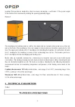
The furnace chamber consists of a slanting and sliding cascade cast-iron grate. These grates are
controlled by the grate lever on the side of the boiler. The volume of incoming secondary air can be
mechanically adjusted (in the case of the H425 EKO water heater) by revolving valves located on
both sides of the boiler.
Setting up secondary air flow for brown coal (nut 1):
Under normal operation with nominal power output and when using brown coal (fossil fuel), the
valves are open as it is showed on Picture A. It means that the handles of both revolving valves (left
and right side) are in the position that they point exactly towards the marked line.
Picture A
Setting up secondary air flow for wood (maximum length of 39 cm):
Under normal operation with nominal power output and when using wood (biological fuel), the
valves are open as it is showed on Picture B. It means that the handles of both revolving valves (left
and right side) are in the maximum opening position.


