Interfaces
Sinergy S II Series Series UPS User Instruction Manual
19
equipment. The interface ports will send On Battery and Low Battery signals to the host computer. The
interface ports will also accept a shutdown inverter signal to conserve battery life.
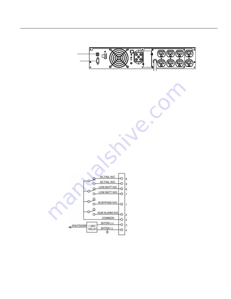
fig. 17: UPS Communications Ports
Installing MopUPS Professional
To establish communications between the UPS and a computer:
1. Connect the computer to the UPS communications port using the supplied USB communications
cable.
NOTE:If a serial connection is required, contact the factory to purchase optional serial cable (part
number CA-2B10S-03).
NOTE:RS232 and USB communications ports cannot be used simultaneously.
2. Insert the supplied software CD into the computer’s CD-ROM drive.
3. Once the CD is inserted into the drive, an installation wizard will appear. Follow the installation
instruction from the wizard.
Once MopUPS Professional is installed and launched, the user manual can be accessed by clicking on the
Help button. If further assistance is needed, contact Technical Service at 800-327-8801, option 3 or email:
[email protected].
Optional Isolated
Contacts Card
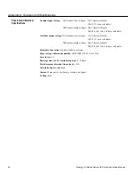
Below are the descriptions of the interface signals for the isolated contacts card that may be installed into
the COM slot. This optional card provides potential-free signaling contacts and a shutdown input.
Fig. 18: Isolated Contacts Card Interface Signals
INV SHUTDOWN
This input (pin 3) is enabled with a high signal (+5 V to +12 V with respect to pin 4 (0 V)) and when
enabled, switches off the UPS after a mains failure has occurred. After the mains have been reestablished,
the UPS starts again independent of this signal status. This input must be high for one (1) second before
shut off will occur.
Serial Port
USB Port
Содержание S07KXAU
Страница 3: ......


