Theory of Operation
Sinergy S II Series Series UPS User Instruction Manual
11
Bypass Mode
In the event of a brief overload on the UPS or internal UPS failure, the load is immediately supplied directly
from the mains via an automatic internal bypass. As soon as normal status is reestablished, an automatic
switch over to inverter operation is performed.
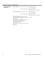
• < 110% warning
• 110% - 130%: 12 seconds, switches to bypass
• >130% - 1.5 seconds, switches to bypass
Contact technical service for further details
Front Panel Display
and Control
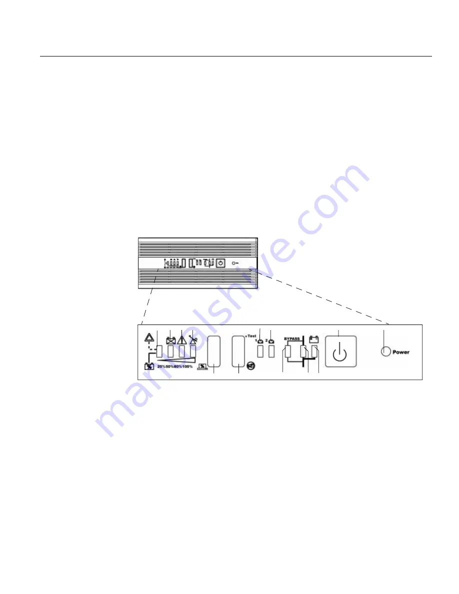
The front panel display contains a series of switches and indicator LED’s that provide the operator with the
current status of the UPS, and the ability to change UPS operational mode.
• Main UPS ON/OFF switch
• A simplified block diagram of the UPS shows the current operational mode of the UPS (i.e. on-line,
on-battery, or on-bypass.)
• Two LED indicators show the current status (ON or OFF) of the controllable receptacle groups 1 and
2.
• Four additional LEDs provide error status, UPS load percentage or battery charge percentage
depending on if the associated front panel button is pressed.
Fig. 9: Front Panel Display
1. Site Wiring Fault LED
8. ON LED
2. Battery Fault LED
9.
Display Selector(Battery Charge/UPS Load% (on LED’s 1-4)
3. UPS Fault LED
10. LED Test/Alarm Reset
4. UPS Overload LED
11. Operation in BYPASS Mode
5. Controllable Receptacle Group 1 On / Off
12. Operation in ON-LINE Mode
6. Controllable Receptacle Group 2 On / Off
13. Output Supplied by Battery
7. Standby (ON / OFF Switch)
5
9
6
4
10
3
2
1
11
7
12
13
8
Содержание S07KXAU
Страница 3: ......


