Service Manual version 1008
OP 1200/1500/1700 (PC920 Intel 945G)
5-49
5.2.9. PC Module Integration
The PC’s individual modules are now ready for final integration to the PC chassis to make a complete
panel PC. The sequence for integration is from the motherboard, the HDD module, the toucshcreen
controller, the expansion door, the CD-ROM/FDD module, the display module, the inverter, the power
supply, the riser card and then followed by the PC cover module.
Follow the steps below to integrate the individual modules to the system chassis.
5.2.9.1. Motherboard Integration
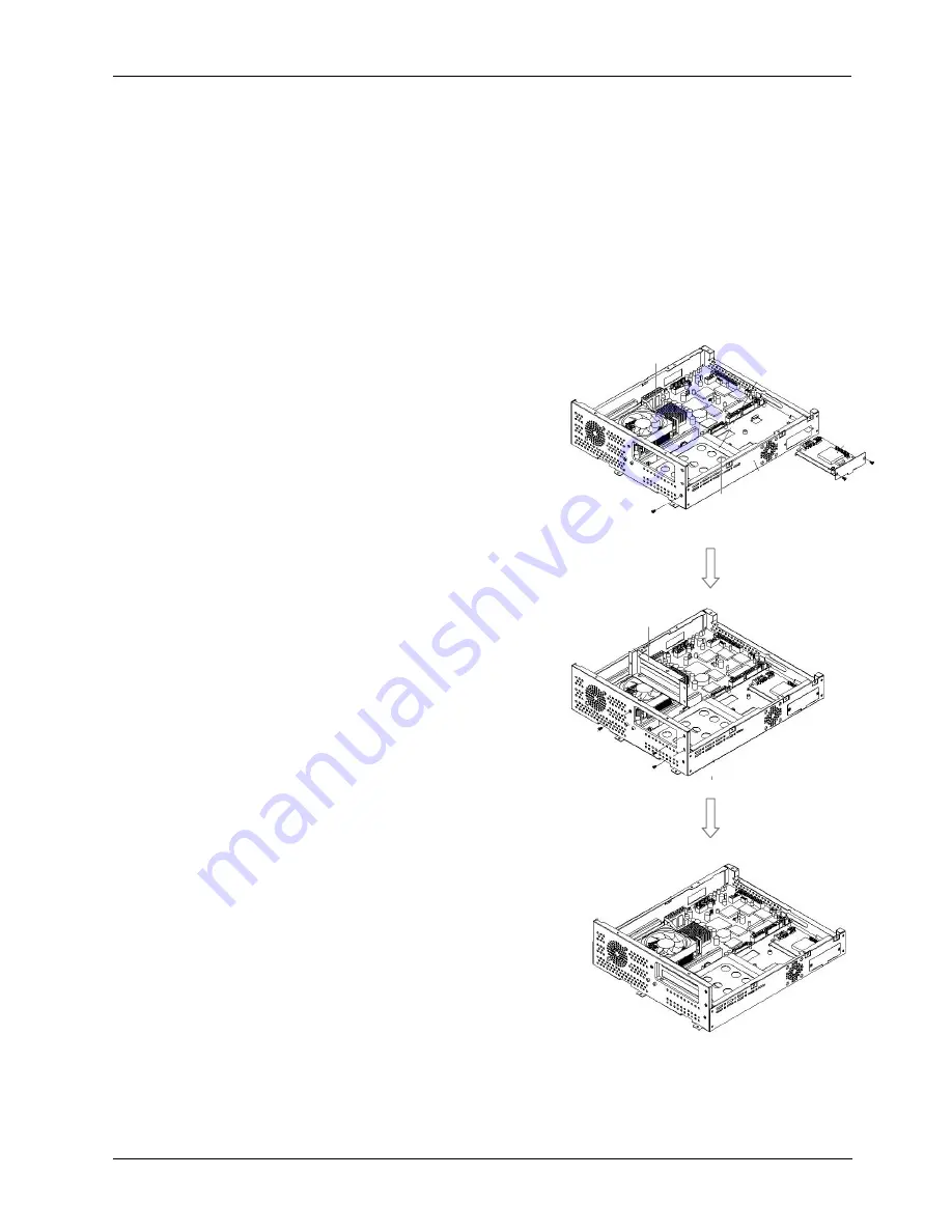
1. The motherboard (2) is the first component to be assembled to the PC chassis (A). Make sure the
CPU with cooling fan and DDR are already properly installed to the motherboard. From your point
of view, the expansion opening is at your right side. The motherboard module is to be installed
to the lower side of the chassis.
2. Tape the motherboard insulator (1) to the
chassis first. The insulator is to isolate the
electronic components on the reverse side of the
motherboard from the metal compartment to
prevent short circuitry caused during system
operation.
3. There are eight screws holes on the motherboard.
Retain the motherboard (2) to the chassis with
eight PMS M3*5 screws.
5.2.9.2. HDD Module Integration
4. There are two clamps at the bottom side used to
hold the HDD module to the chassis. Insert the
HDD module to the chassis and clamp it into place.
Retain the HDD module (3) to the chassis with
one FMS M3*5 screw at the upper side of the
chassis.
5. Connect the other end of the 20P*2 HDD ribbon
cable to
IDE1
at the left upper side of the
motherboard.
5.2.9.3. Touchscreen Controller Integration
6.
Insert the touchscreen controller bracket (4)
to the chassis from the opening at the left
upper side opening and retain it to the chassis
with two FMS M3*5 screws.
7. Connect the other end of the 5P*2 flat cable from
the controller to
COM3
at left upper side of the
motherboard.
8. Connect the other end of the 2P power wire to the
CN1
on the motherboard.
5.2.9.4. Expansion Door Integration
9. Retain the expansion door (5) to the opening at
the right side of the chassis with three FMS
M3*5 screws.
(4)
FMS 3*5 (2)
(5)
FMS 3*5 (3)
(3)
FMS 3*5 (1)
(2)
PMS 3*5 (8)
Содержание OP 1200
Страница 8: ......
Страница 32: ...Service Manual version 1008 OP 1200 1500 1700 PC920 Intel 945G 4 24...
Страница 79: ...Service Manual version 1008 OP 1200 1500 1700 PC920 Intel 945G 6 71...
Страница 91: ...Service Manual version 1008 OP 1200 1500 1700 PC920 Intel 945G 7 83...
Страница 106: ...Service Manual version 1008 OP 1200 1500 1700 PC920 Intel 945G 7 98...
Страница 109: ...Service Manual version 1008 OP 1200 1500 1700 PC920 Intel 945G 7 101...
Страница 112: ...Service Manual version 1008 OP 1200 1500 1700 PC920 Intel 945G 7 104...

