background image

Service Manual version 1008

OP 1200/1500/1700 (PC920 Intel 945G)

5-45

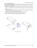
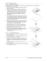
5.2.4. Power Module Assembly

The power supply is to be integrated to a power bay before it is installed to the panel PC. The following

figure illustrates the steps to assemble the ATX power module. For the specification of the power

supply, please refer to APPENDIX.
1. Attach the power bracket (2) to the power supply (3) and fix them together with two FMS 6#32 5L

screws. This small bracket is used to prevent the power supply from moving around in the power

bay.

2. Insert the power supply to the power bay (1) and fix them together with two FMS M3*5 and two

FMS 6#32 5L screws.

3. Protect the front section power cables with a nylon protector. The nylon protector is to prevent

the power wires from being cut by the metal brackets.

4. Attach two nylon adhesive cable tie bases to the side of the power bracket.
5. Retain the power cable bundle to the mounting base with a cable tie.
6. Insert a power switch (4) extension cable to the power bracket (1).

(1)

(2)

(3)

The power cable
coming out from
the opening and
connected to the
MB’s ATX power
connector.

FMS 3*5 (2)
FMS 6#32 5L (2)

P

OWER MODULE ASSEMBLY

(4)

Содержание OP 1200

Страница 1: ...12 1 15 17 Intel Core 2 Duo Industrial Panel PC with Versatile Bezel Design Panel PC OP 1200 1500 1700 MB PC920 System Chipset Intel 945G Service Manual Version 2807 Version v1008 August 2010...

Страница 2: ...an radiate radio frequency energy and if not installed and used in accordance with the instructions may cause harmful interference to radio communications However there is no guarantee that interferen...

Страница 3: ...Pedestal set Accessory box Power cord 90o x 1 Utilities drivers user manual CD diskette x 1 Panel mounting kit optional x 1 set Make sure that all of the items listed above are present If any of the...

Страница 4: ...stall the system on a reliable surface to prevent damage caused by dropping 8 Disconnect the power cord from the system before any installation Make sure both the system and the external devices are t...

Страница 5: ...C 4 25 4 1 WHAT CONTAINS IN EACH MODULE 4 26 4 2 DISASSEMBLING THE PANEL PC 4 26 4 2 1 Disassembling the Display Module 4 28 4 2 2 Knocking down the panel PC s Individual Modules 4 29 4 2 2 1 Disassem...

Страница 6: ...uchscreen Power Connector 6 60 6 1 6 4 PWR1 CD ROM Power Connector 6 60 6 1 6 5 INV1 LCD Inverter Connector 6 60 6 1 6 6 USB1 2 USB Port Connector 6 61 6 1 6 7 LCD1 LCD Connector 6 61 6 1 6 8 IDE1 PAT...

Страница 7: ...Integrated Peripherals 7 89 7 4 6 Power Management Setup 7 91 7 4 7 PnP PCI Configuration 7 94 7 4 8 PC Health Status 7 95 7 4 9 Load Fail Safe Defaults 7 97 7 4 10 Load Optimized Defaults 7 98 7 4 11...

Страница 8: ......

Страница 9: ...20 Intel 945G 1 1 1 1 I In nt tr ro od du uc ct ti io on n This chapter provides background information and detail specification on the OP SERIES Sections in this chapter include General Information W...

Страница 10: ...For their industrial automation there is one thing in common i e space is always a premium and system stability is always a must in their environmental applications Fully configurable and with its ve...

Страница 11: ...provides instructions to help you to use the system as soon as possible Chapter 3 details the panel PC s various mounting options by graphical illustrations Chapter 4 helps you to knock down the syste...

Страница 12: ...ce cd m2 250 or above OP 1700 17 color TFT 1280 1024 Luminance cd m2 420 or above Integrated 2D 3D graphics engine 4X AGP Supports Dynamic Video Memory Technology DVMT Supporting LCD VGA Standard I Os...

Страница 13: ...e Monitors 5VSB VBAT 1 5V 3 3V 5V 12V and processor voltages Monitors processor and chassis fan speeds Controls processor chassis fan speed and failure alarm Automatic fan on off control Read back cap...

Страница 14: ...4 283 mm small bezel OP 1500S 395 320 mm small bezel OP 1700S 426 350 mm small bezel OP 1200B 405 330 mm big bezel OP 1500B 448 371 mm big bezel OP 1700B 478 401 mm big bezel OP 1200A 405 330 mm alumi...

Страница 15: ...1200 1500 1700 PC920 Intel 945G 2 7 2 2 U Us si in ng g t th he e S Sy ys st te em m Identifying the System Panel PC I O outlets Panel PC dimension Powering up the System Running the BIOS Setup Operat...

Страница 16: ...ment of the OP 1200 1500 1700 The OP SERIES s front view appears as below The illustrations of the OP 1200 1500 1700 may differ slightly because the OP SERIES system series has three different LCD siz...

Страница 17: ...d all the I O ports are located at the rear cover of the panel PC 1 Speaker out 2 Line in 3 MIC in 4 2 channel DIO 5 5 12V DC out 6 External FDD 7 VR brightness 8 PS 2 Mouse 9 PS 2 Keyboard 10 Etherne...

Страница 18: ...is for PS 2 keyboard connection 10 Ethernet RJ 45 The system provides a 100 10 Base T Ethernet interface 11 USB 2 These two ports are for USB device connection 12 COM1 This port is for serial device c...

Страница 19: ...3 OP SERIES Dimension 2 3 1 OP 1200 The OP 1200 s chassis size is shown below This does not include the dimension of the bezel 2 3 2 OP 1500 The OP 1500 s chassis size is shown below This does not in...

Страница 20: ...Service Manual version 1008 OP 1200 1500 1700 PC920 Intel 945G 2 12 2 3 3 OP 1700 The OP 1700 s chassis size is shown below This does not include the dimension of the bezel OP 1700 DIMENSION...

Страница 21: ...t the 3 pin female end of the power cord to the AC inlet located at the right rear lower side of the panel PC Plug the 3 pin male end to an AC power socket 2 If there are any other peripheral devices...

Страница 22: ...AM and compare them to the equipment check conducted during the power on self test POST If any error or mismatch occurs an error message will be shown on the screen and the computer will be prompted t...

Страница 23: ...g O Op pt ti io on ns s The OP SERIES system is designed for universal mounting to fit into different system enclosures for various environmental applications This chapter highlights the steps of dif...

Страница 24: ...d with a small bezel The front bezel size is identical to the computer s chassis size This type of bezel is mainly designed for Kiosk integration when the Kiosk cabinet is with a curve surface and doe...

Страница 25: ...inly designed for panel mounting or for Kiosk integration when the Kiosk cabinet is of flat surface and allows the computer to be fixed to the Kiosk cabinet directly from inside When integrating the O...

Страница 26: ...ezel The OP SERIES A is an industrial panel PC with an aluminum alloy bezel This aluminum alloy bezel is mainly designed for panel mounting It not only strengthens the system s framework but also beau...

Страница 27: ...ounted here OP SERIES B MOUNTING WITH L SHAPE MOUNTING BRACKETS Mounting brackets to be mounted here 3 2 L shape Mounting Brackets The OP SERIES system provides a pair of L shape mounting brackets for...

Страница 28: ...500 1700 PC920 Intel 945G 3 20 3 2 1 OP 1200 Panel Mount The following figures illustrate the distance between the screw holes on the bezel to be fixed with the L shape mounting brackets OP 1200 WITH...

Страница 29: ...500 1700 PC920 Intel 945G 3 21 3 2 2 OP 1500 Panel Mount The following figures illustrate the distance between the screw holes on the bezel to be fixed with the L shape mounting brackets OP 1500 WITH...

Страница 30: ...500 1700 PC920 Intel 945G 3 22 3 2 3 OP 1700 Panel Mount The following figures illustrate the distance between the screw holes on the bezel to be fixed with the L shape mounting brackets OP 1700 WITH...

Страница 31: ...ile Applications The OP SERIES system provides 1 set of VESA mounting holes 75 75mm on the rear side of the chassis System integrators can design their special wall mount brackets per the VESA holes o...

Страница 32: ...Service Manual version 1008 OP 1200 1500 1700 PC920 Intel 945G 4 24...

Страница 33: ...1200 1500 1700 PC920 Intel 945G 4 25 4 4 K Kn no oc ck ki in ng g d do ow wn n t th he e P Pa an ne el l P PC C This chapter highlights how to knock down the system into parts to access the modules or...

Страница 34: ...ower Supply Module 3 Riser Card Module 3 PC I O Cover Module The following steps highlight the procedures to knock the panel PC into individual modules 1 Remove the metal PC I O cover by loosening the...

Страница 35: ...Service Manual version 1008 OP 1200 1500 1700 PC920 Intel 945G 4 27 The panel PC is now knocked down into individual modules...

Страница 36: ...the two modules together 2 Remove the LCD panel 1 from the LCD holder 2 by unscrewing the four screws used to retain them together 3 For OP 1200 detach the LCD power wires from the inverter and remove...

Страница 37: ...of three I O boards All the onboard I O signal of the OP SERIES s motherboard is connected to these boards for external device connection 1 Detach the I O board module 1 from the PC I O cover 2 by un...

Страница 38: ...remove the two retaining screws 4 1 2 3 Disassembling the Power Supply Module 1 Loosen all the cable ties used to tie the power cables on the power module 2 2 Remove the power switch extension cable 1...

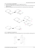
Страница 39: ...2 from the CD ROM FDD module 2 2 Remove the CD ROM module 3 and FDD 4 from the device bracket 5 by loosening the four retaining screws 3 Detach the CD ROM board 6 from the CD ROM 7 by loosening the t...

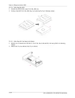
Страница 40: ...tach the HDD ribbon cable from the HDD 1 2 Remove the HDD from the HDD bay by loosening the four retaining screws 4 1 2 7 Detaching the Touchscreen Controller 1 Detach the tocuhscreen controller 1 fro...

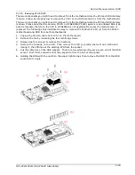
Страница 41: ...is replaced The following steps illustrate the way to remove the Pentium M CPU 2 from the PC920 motherboard and DDR from both motherboards 1 Unplug the CPU fan cable from FAN1 on the motherboard 2 Re...

Страница 42: ...5 34 5 5 B Bu ui il ld di in ng g u up p t th he e P Pa an ne el l P PC C This chapter overviews the installation of the OP SERIES s internal components and devices Sections include Display Module Ass...

Страница 43: ...play module and the other PC module In terms of LCD size the OP SERIES has three models one 12 1 another 15 and the other 17 The assembly of the three models is basically the same except the LCD assem...

Страница 44: ...945G 5 36 The following diagram shows the system major parts that make up the OP 1500 main system 1 A 5 FMS M3 5 3 6 PMS 3 6 6 FMS M3 5 9 12 2 PMS 3 5 8 3 FMS M3 5 1 4 FMS M3 5 2 FMS M3 5 3 8 9 FMS M3...

Страница 45: ...o fix the touchscreen 2 to the front bezel The metal brackets have to be taped with foam sponges 3 Put the touchscreen to the bezel with its active side facing downwards and its white flat cable at th...

Страница 46: ...LCD module 1 Attach the insulator to the inverter 2 The inverter cable is a 4 pin to 4 pin wire with wafer connectors at both sides Connect one end to inverter first 3 The inverter module is to be fix...

Страница 47: ...lustrates the steps to integrate OP 1500 170 LCD module 1 There are two LCD brackets 1 used to fix to the LCD panel to the LCD holder from the left right sides Fix the LCD brackets 1 to the LCD panel...

Страница 48: ...nd the front bezel module 1 together with six PMS M3 8 screws 2 Make sure the LCD s pink white power wires come out from two rectangle openings at the left upper and lower sides of the LCD holder And...

Страница 49: ...or maintain the system The hard disk drive can be removed by releasing the thumbscrew at the upper side of the chassis By removing the PC I O cover 7 the internal components such as CPU DDR and power...

Страница 50: ...r OP SERIES system follow the instructions below 1 Pull the CPU lever up by pulling it outwards a little bit then upwards To insert the CPU 1 into the socket 2 the notch on the corner of the CPU the c...

Страница 51: ...ry module with the notch on the upper right corner then insert the memory module into the DDR2 socket at 90 angle 4 Push the two eject levers toward the vertical posts until they click into place The...

Страница 52: ...2 There is a 2P black red power wire 4 to provide the power source for the touchscreen Connect one end to P2 on the controller 3 Make the controller s coach chip 5 at the upper side Retain the touchsc...

Страница 53: ...he power supply from moving around in the power bay 2 Insert the power supply to the power bay 1 and fix them together with two FMS M3 5 and two FMS 6 32 5L screws 3 Protect the front section power ca...

Страница 54: ...4 and fix them together with two IMS M2 2 25 screws 3 There is a 40 pin CD ROM ribbon cable 7 Connect one end to the CD ROM board 4 Attach one end of the 26 pin FDD flat cable to the slim floppy disk...

Страница 55: ...ed with the system fix the two metal brackets 1 to the expansion door 2 with two TMS 3 6 screws If an add on card is to be used with the system then only fix one metal cover to the expansion door 5 2...

Страница 56: ...he filter cover set to the PC metal cover with four FMS M3 5 screws 3 Attach the IO 006 I O board 1 to the I O bracket 3 and fix them together with two 4 12 secure bolts and one FMS 3 5 screw 4 Attach...

Страница 57: ...reverse side of the motherboard from the metal compartment to prevent short circuitry caused during system operation 3 There are eight screws holes on the motherboard Retain the motherboard 2 to the c...

Страница 58: ...0 is a 7P to 4P cable with wafer connectors at both sides Insert the 7P end into the left opening of the inverter insulator and have it connected to CN1 on the inverter first 11 Connect the OP 1500 17...

Страница 59: ...of the power cable to the HDD 24 Connect the small 4 pole end of the power cable to the CD ROM board 5 2 9 8 Riser Card Integration 25 Have the riser card module 10 firmly plugged to the ESIA slot on...

Страница 60: ...O O B Bo oa ar rd ds s The system controller used in the OP SERIES system is a special design Intel LGA775 Socket Core 2 Duo multimedia motherboard All the onboard signal is connected to the external...

Страница 61: ...CPU Onboard features include four serial ports one multi mode Parallel ports a floppy drive controller and a PS 2 keyboard PS 2 mouse interface The built in high speed PCI IDE controller supports both...

Страница 62: ...erface x 1 Internal Keyboard Interface x 1 PS 2 Mouse Interface x 1 USB Interface x 6 supports USB 2 0 devices internal x4 port external x2 port IrDA 6 pin header Support IrDA version 1 0 SIR Consumer...

Страница 63: ...tel 945G 6 55 Automatic fan on off control Read back capability that displays temperature voltage and fan speed Supporting Intel processor thermal diode output real processor temperature Expansion Bus...

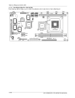
Страница 64: ...Service Manual version 1008 OP 1200 1500 1700 PC920 Intel 945G 6 56 6 1 3 Locating Jumpers Connectors The following figure helps you to locate the jumpers and connectors on the motherboard...

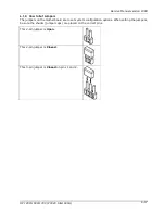
Страница 65: ...How to Set Jumpers The jumpers on the motherboard are to set system configuration options When setting the jumpers be sure the shunts jumper caps are placed on the correct pins This 2 pin jumper is Op...

Страница 66: ...PC920 Intel 945G 6 58 6 1 5 Jumpers Jumper Setting The table below lists the function of each jumper The related jumper settings are shown in the coming sections Jumper Description JP3 Clear CMOS 6 1...

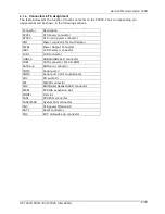
Страница 67: ...connector CN1 Power connector for touchscreen PWR1 Power Output Connector INV1 LCD Inverter connector LCD1 LCD connector USB1 2 USB1 USB2 port connector IDE1 PATA connector For CD ROM SATA1 4 SATA1 4...

Страница 68: ...are aligned Its pin assignments are listed below Pin Signal Pin Signal 3 3V 11 3 3V 2 3 3V 12 12V 3 Gnd 13 Gnd 4 5V 14 PSON 5 Gnd 15 Gnd 6 5V 16 Gnd 7 Gnd 17 Gnd 8 PWROK 18 5V 9 SB5V 19 5V 10 12V 20 5...

Страница 69: ...CC 3 USB P4 4 USB P5 5 USB P4 6 USB P5 7 GND 8 GND 9 KEY 10 HEAD 6 1 6 7 LCD1 LCD Connector Pin Signal Pin Signal 1 YA0M 2 YA0P 3 YA1M 4 YA1P 5 YA2M 6 YA2P 7 GND 8 CLKAM 9 CLKAP 10 YA3M 11 YA3P 12 YB0...

Страница 70: ...D 3 DATA 7 4 DATA 8 5 DATA 6 6 DATA 9 7 DATA 5 8 DATA10 9 DATA 4 10 DATA11 11 DATA 3 12 DATA12 13 DATA 2 14 DATA13 15 DATA 1 16 DATA14 17 DATA 0 18 DATA15 19 GND 20 NC 21 IDEREQ 22 GND 23 IOW 24 GND 2...

Страница 71: ...6 CTS 7 DTR 422RX 8 RI 9 GND 10 KEY 6 1 6 11 COM3 COM 3 is an internal RS 232 reserved for touchscreen Its corresponding pin assignment is listed as below Pin Signal Pin Signal 1 DCD 2 DSR 3 RXD 4 RT...

Страница 72: ...ND 19 USB P2 20 EXT KBDAT 21 USB P2 22 EXT KBCLK 23 USB P3 24 EXT MSDAT 25 USB P3 26 EXT MSCLK 6 1 6 15 IOINF 1 I O Connector The PC920 s onboard I O signal for LAN USB keyboard mouse VGA COM ports an...

Страница 73: ...PCI ISA Expansion Slot The PC920 provides an ISA PCI slot for ISA and PCI device expansion B1 B2 B3 B4 B5 B6 B7 B31 D1 D2 D3 D4 D18 E1 E2 E3 E4 E5 E6 E7 E31 G1 G2 G3 G4 G19 A1 A2 A3 A4 A5 A6 A7 A31 C1...

Страница 74: ...F18 AD27 B18 DRQ1 E18 AD28 A18 SA13 F19 AD25 B19 REF E19 AD26 A19 SA12 F20 CBE3 B20 ATCLK E20 AD24 A20 SA11 F21 AD23 B21 IRQ7 E21 AD22 A21 SA10 F22 AD21 B22 IRQ6 E22 AD20 A22 SA9 F23 AD19 B23 IRQ5 E23...

Страница 75: ...SD13 H17 VCC D17 MASTER G17 VCC C17 SD14 H18 GND D18 GND G18 GND C18 SD15 H19 GND G19 GND 6 1 6 17 FAN 1 3 FAN Connector Pin Signal 1 GND 2 12V 3 FAN SPEED DECECT 6 1 6 18 CN3 ATX Power on Switch Pin...

Страница 76: ...ERIES I O Boards The IO 005 and IO 006 are two docking boards used to connect all the I O signal from OP SERIES s Motherboard to the exterior of the system for external device connection This section...

Страница 77: ...Jumper Setting The table below lists the function of each jumper on IO 005 JP3 COM1 pin 9 power selection JP2 COM2 pin 9 power selection JP1 COM4 pin 9 power selection The OP SERIES onboard COM port p...

Страница 78: ...lect ADDRES 200H OR 208H Read DIO IN BIT0 BIT3 IN DIO PORT ADDRES BIT0 3 WRITE DIO OUT BIT0 3 IN DIO PORT ADDRES BIT4 7 JP2 CN4 DIO port pin 2 select 1 2 DIO IN Bit 0 2 3 DIO OUT Bit 2 JP1 CN4 DIO por...

Страница 79: ...Service Manual version 1008 OP 1200 1500 1700 PC920 Intel 945G 6 71...

Страница 80: ...g sections Keyboard Keyboard connector Mouse Mouse connector COM1 Serial port 1 3F8 COM2 Serial port 2 2F8 COM4 Serial port 4 2E8 DC Power DC power 5V 12VC output LPT Parallel port CRT CRT display con...

Страница 81: ...OM4 DB 9 Pin Signal Pin Signal 1 DCD 6 DSR 2 RXD 7 RTS 3 TXD 8 CTS 4 DTR 9 RI 5V 12V 5 GND 6 2 3 4 DC Power DC Power Output Pin Signal Pin Signal 1 GND 5 5V 2 GND 6 12V 3 5V 7 GND 4 12V 8 GND 6 2 3 5...

Страница 82: ...al 1 RWC 6 WP 11 RDATA 2 INDEX 7 TRAK0 12 HEAD 3 MOA 8 WE 13 DSKCHG 4 DSA 9 WD 14 GND 5 DIR 10 STEP 15 GND 6 2 3 8 J11 USB 1 USB2 Connector USB1 USB2 Pin Signal Pin Signal 1 USBVCC 1 USBVCC 2 Data 2 D...

Страница 83: ...Service Manual version 1008 OP 1200 1500 1700 PC920 Intel 945G 6 75 6 2 3 12 LINE 1 Pin Signal 1 Right CHI 2 NC 3 NC 4 Left CH 5 GND 6 2 3 13 SPK 1 Pin Signal 1 Right CHI 2 NC 3 NC 4 Left CH 5 GND...

Страница 84: ...tup Utility displays the system s configuration status and provides options to set system parameters The parameters are stored in battery backed up CMOS RAM that saves this information even when the p...

Страница 85: ...y When trying to resolve IRQ conflicts When making changes to the Power Management configuration When changing the User or Supervisor password The BIOS setup program is stored in ROM which can be acce...

Страница 86: ...Status Page Setup Menu and Option Page Setup Menu Exit current page and return to Main Menu PgUp Increase the numeric value or make changes PgDn Decrease the numeric value or make changes F1 General h...

Страница 87: ...lity displays a list of the options that are available A highlight indicates which option is currently selected Use the cursor arrow keys to move the highlight to other options When an option is highl...

Страница 88: ...page auto detects the temperature voltage and fan speed Frequency Voltage Control This setup page includes the CPU DDR PCI frequency setting Load Fail Safe Defaults BIOS Defaults indicates the most a...

Страница 89: ...onth year The year from 1994 through 2079 Time The Time item show the current time held system If you are running a Windows OS these items are automatically updated whenever you make changes to the Wi...

Страница 90: ...e displays the location of the safe non data area on a hard disk that is used for parking the read write head Sector displays the number of sectors available on the HDD A sector is the smallest unit o...

Страница 91: ...Service Manual version 1008 OP 1200 1500 1700 PC920 Intel 945G 7 83...

Страница 92: ...or hard disk partition table Phoenix AwardBIOS CMOS Setup Utility Advanced BIOS Features CPU Feature Press Enter Item Help Hard Disk Boot Priority Press Enter Menu Level Virus Warning Disabled Allows...

Страница 93: ...ey is active when the system is started Gate A20 Option This item defines how the system handles legacy software that was written for an earlier generation of processors Leave this item at the default...

Страница 94: ...e running the OS 2 operating system Otherwise leave this item at the default Report No FDD For Win 95 If you are using Windows 95 98 without a floppy disk drive select Enabled to release IRQ6 This is...

Страница 95: ...result The options are Enabled or Disabled Memory Hole at 15M 16M You can reserve this area of system memory for ISA adapter ROM When this area is reserved it cannot be cached The user information of...

Страница 96: ...PC920 Intel 945G 7 88 This item is to set DVMT FIXED mode memory size The options are 64MB 128MB 224MB Boot Display This item is to select the boot display from VBIOS Default or CRT LCD Panel Scaling...

Страница 97: ...is option defines the operation of peripheral components on the system s input output ports Phoenix AwardBIOS CMOS Setup Utility Integrated Peripherals OnChip IDE Device Press Enter Item Help OnChip D...

Страница 98: ...face supports Modes 0 through 4 provide successively increased performance In Auto mode the system automatically determines the best mode for each device The options are Auto Mode 0 Mode 1 Mode 2 Mode...

Страница 99: ...Service Manual version 1008 OP 1200 1500 1700 PC920 Intel 945G 7 91 The item is to setting the On Chip SATA Function...

Страница 100: ...s for disable enable EHCI controller only Support the high speed USB device The options are Enabled or Disabled USB Keyboard Support Select Enabled if your system contains a Universal Serial Bus USB c...

Страница 101: ...8 3E8 2E8 Disabled Onboard UART 1 UART 2 UART 3 UART 4 IRQ This item is to select an IRQ for the serial ports The options are IRQ4 IRQ3 IRQ10 IRQ11 IRQ9 IRQ5 COM2 Selectable type This item is to selec...

Страница 102: ...Service Manual version 1008 OP 1200 1500 1700 PC920 Intel 945G 7 94 The options are SPP EPP ECP ECP EPP Normal DIO Port Address This item is to select the DIO port I O address The options are 200 208...

Страница 103: ...modem to the main board Wake On Modem connector for this feature to work The default setting is 3 Suspend Mode The CPU clock will be stopped and the video signal will be suspended if no Power Manageme...

Страница 104: ...fields become available and you can set the date day of the month hour minute and second to turn on your system When set to 0 zero for the day of the month the alarm will power on your system every d...

Страница 105: ...es are controlled manually assign each system interrupt a type depending on the type of device using the interrupt IRQ3 4 5 7 9 10 11 12 14 15 assigned to This item allows you to determine the IRQ ass...

Страница 106: ...Service Manual version 1008 OP 1200 1500 1700 PC920 Intel 945G 7 98...

Страница 107: ...ntrol Mode This item is to select Fan control mode The options are Temp Cruise or Disabled CPU Fan Control Mode This item is to select Fan control mode The options are Temp Cruise Smart fan or Disable...

Страница 108: ...tem parameters that the system would be in safe configuration Phoenix AwardBIOS CMOS Setup Utility Standard CMOS Feature Frequency Voltage Control Advanced BOIS Features Load Fail Safe Defaults Advanc...

Страница 109: ...Service Manual version 1008 OP 1200 1500 1700 PC920 Intel 945G 7 101...

Страница 110: ...t password then the current password the ROM password or the use defined password stored in the ROM needs to be entered first The following message will appear on the screen Confirm Password Enter the...

Страница 111: ...Standard CMOS Feature Frequency Voltage Control Advanced BOIS Features Load Fail Safe Defaults Advanced Chipset Features Load Optimized Defaults Integrated Peripherals Set Supervisor Password Power Ma...

Страница 112: ...Service Manual version 1008 OP 1200 1500 1700 PC920 Intel 945G 7 104...

Страница 113: ...1200 1500 1700 PC920 Intel 945G 8 105 8 8 S So of ft tw wa ar re e D Dr ri iv ve er rs s I In ns st ta al ll la at ti io on n The chapter introduces the PC920 onboard VGA Ethernet Audio and the respe...

Страница 114: ...ebsite http www intel com 8 2 Ethernet Drivers The PC920 provides a 10 100 Base T fast Ethernet The Ethernet chipset used on PC920 is Realtek RTL8100B The PC920 Ethernet drive diskette or CD diskette...

Страница 115: ...It adopts Share System Memory architecture that can flexibly utilize the frame buffer size up to 64MB The PC920 XGA driver diskettes contain the following driver Intel 945G VGA drivers for Windows 95...

Страница 116: ...contains the following drivers The Realtek A406 audio drivers contain the following drivers Windows 95 95OSR2 Windows 98 Windows 2000 Windows NT Windows ME Windows XP The related drivers are stored un...

Страница 117: ...d in the following route Drivers Touch screen Driver Elo Resistive SAW Touch If your use Taiwan Resistive brand touch the panel PC touchscreen driver are stored in the following route Drivers Touch sc...

Страница 118: ...ntel 945G integrated Ethernet Chipset Realtek RTL8100B Audio Chipset Realtek ALC202A Find the correct drivers from the correct directory and execute the execution files All the related drivers are sto...

Страница 119: ...White 400 cd m2 Typ Power Consumption 6 8 Watt Typ Weight 655g Max Display Operating Mode Transmissive mode normally white Surface Treatment Anti glare treatment A 1 2 Absolute Maximum Ratings of Envi...

Страница 120: ...Service Manual version 1008 OP 1200 1500 1700 PC920 Intel 945G 8 112 Power Consumption PBL 6 18 7 52 Watt Life Time 50 000 Hr...

Страница 121: ...024 horiz By 768 vert Pixels RGB strip arrangement Color Depth 16M colors 6 bit with FRC Luminance White 250 cd m2 Center 1 points Typ Viewing Angle CR 10 R L 130 Typ U D 100 Typ Power Consumption Tot...

Страница 122: ...3H anti glare treatment Note 1 System should warm up for at least one hour A 2 2 2 Absolute Maximum Ratings Item Symbol Min Max Unit Note LCD Logic LCD Drive VDD 0 3 3 6 Volt Note 1 Backlight CCFL Cur...

Страница 123: ...lowing display image Typ Value display pattern is 256 gray scale bar NOTE 2 VCM Common Mode Voltage of LVDS Input A 2 2 5 Environmental Absolute Maximum Ratings Ta 25o C Item Symbol Condition Min Max...

Страница 124: ...onal Outline Dimension 358 5 H x 296 5 V x 17 D mm Typ Pixel Pitch 0 264 mm x 0 264 mm Pixel Format 1280 horiz by 1024 vert pixels RGB strip arrangement Color Depth 16 2M colors 6 bit with FRC Luminan...

Страница 125: ...The Digital I O is of TTL interface It is controlled via software programming Digital I O Programming Input output address 208H In_Data 0 3 SD0 SD1 Out_Data 0 3 SD4 SD7 EXAMPLE 10 REM Digital I O exa...

Страница 126: ...During the power up the DiskOnChip drivers will be automatically loaded into the system memory 5 At this time the DiskOnChip can be accessed as any disk drive 6 If it is the only disk in the system it...

Страница 127: ...F0 Clear math co processor 0F1 Reset math co processor 0F8 0FF Math co processor 1F0 1F8 Fixed disk 200 207 Game Port not used 443 Watchdog timer 143 Watchdog timer 208 DIO port 2E8 Serial port 4 2F8...

Страница 128: ...the client system must have a network card with chipset that supports the Wake On LAN and an ATX power supply meeting 2 01 with at least 720mA standby current is also required to support the Ethernet...

Страница 129: ...am installation is not needed Just open the MAGPAC EXE then the following screen will pop up The remote computer can be waken up by selecting the MAGIC PACKETS POWER ON ONE HOST as shown below Do not...

Страница 130: ...the following screen will pop up If the OS is Windows NT 4 0 or 2000 or XP then you need to enter DOS mode to run ipconfig exe to obtain the MAC The adapter address is the LAN card s MAC address 4 Aft...

Страница 131: ...945G 8 123 F First MB Memory Map Address range Hex Device F000h FFFFh System ROM CC00h EFFFh Unused C000h CBFFh Expansion ROM B800h BFFFh CGA EGA VGA text B000h B7FFh Unused A000h AFFFh EGA VGA graph...

Страница 132: ...Ripple Noise Min Max Peak 1 3 3V 5 50mV 0 5A 14 0A 2 5V 5 50mV 0 3A 18 0A 3 12V 5 120mV 1 0A 14 0A 16 0A 4 12V 5 120mV 0 0A 0 5A 5 5VSB 5 100mV 0 0A 2 0A 2 5A 12V 3 3V 5V 12V will have the regulation...

Страница 133: ...e output voltage drops below 0 5 volts and is latched off The 12V output shall not exceed 24 amp under the same ramp conditions starting at full load before it is latched off Power Good Signal The pow...

Страница 134: ...Unit Vin 115VAC 90 115 135 VACrms Vin 230VAC 180 230 265 VACrms Vin Frequency 47 63 Hz Normal voltages for test purpose are considered to be within 1 0V of normal Inrush Current Cold start 25o C 115V...

Страница 135: ...ions Plane of vibration to be along mutually perpendicular axes Shock The subject power supply will withstand the following imposed conditions without experiencing non recoverable failure or deviation...

Отзывы: