


Service Manual version 1008
OP 1200/1500/1700 (PC920 Intel 945G)
5-40
D
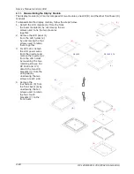
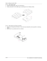
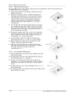
ISPLAY MODULE ASSEMBLY
(2)
(1)
PMS 3*8 (6)
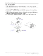
5.1.3. Display Module Integration
After finishing the LCD module installation, the module is to be assembled to the front bezel module
to make a complete display module.
1. Use dust air blower to blow any dust between the LCD and touchscreen before they are integrated
together. Retain the LCD module (2) and the front bezel module (1) together with six PMS M3*8
screws.
2. Make sure the LCD’s pink-white power wires come out from two rectangle openings at the left
upper and lower sides of the LCD holder. And make sure the touchscreen flat cable comes out
from the rectangle opening at the left middle side of the LCD holder.
3. The LVDS cable (3) is to be firmly plugged to the LCD connector located at the rear side of the LCD
panel first. Insert the other end underneath the LCD holder and have it come out from the small
opening at the middle side of the LCD holder.
The display module installation is now completed.
Содержание OP 1200
Страница 8: ......
Страница 32: ...Service Manual version 1008 OP 1200 1500 1700 PC920 Intel 945G 4 24...
Страница 79: ...Service Manual version 1008 OP 1200 1500 1700 PC920 Intel 945G 6 71...
Страница 91: ...Service Manual version 1008 OP 1200 1500 1700 PC920 Intel 945G 7 83...
Страница 106: ...Service Manual version 1008 OP 1200 1500 1700 PC920 Intel 945G 7 98...
Страница 109: ...Service Manual version 1008 OP 1200 1500 1700 PC920 Intel 945G 7 101...
Страница 112: ...Service Manual version 1008 OP 1200 1500 1700 PC920 Intel 945G 7 104...