


10-10
Parame-
ter No.
(Register
No.
(Hex))
Refer-
ence
page
Changes
during
operation
Default
setting
Unit of
setting
Setting
range
Description
Name
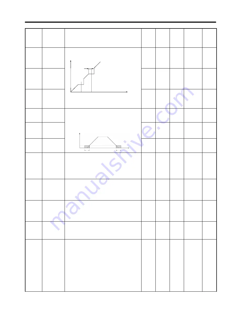
n49
(0131)
Jump fre-
quency 1
Used to set the frequency jump function.
Output
frequency
n51
0.0 to
400
0.1 Hz
(see
note 1)
0.0
No
6-16
n50
(0132)
Jump fre-
quency 2
Frequency
reference
n51
0.0 to
400
0.1 Hz
(see
note 1)
0.0
No
6-16
n51
(0133)
Jump width
reference
Note
These values must satisfy the fol-
lowing condition: n49
y
n50
n50
n49
0.0 to
25.5
0.1 Hz
0.0
No
6-16
n52
(0134)
DC control
current
Set the DC braking current in percentage based
th
t d
t f th I
t
100%
Used to impose DC on the induction motor for
braking control.
0 to
100
1%
50
No
6-5
n53
(0135)
Interruption
DC control
time
g
p
g
on the rated current of the Inverter as 100%.
Output
frequency
0.0 to
25.5
0.1 s
0.5
No
6-5
n54
(0136)
Startup DC
control time
frequency
Time
Minimum
output
frequency
(n14)
n54
n53
0.0 to
25.5
0.1 s
0.0
No
6-5
n55
(0137)
Stall preven-
tion during
deceleration
Used to select a function to change the deceleration
time of the motor automatically so that there will be
no overvoltage imposed on the motor during decel-
eration.
0: Stall prevention during deceleration enabled
1: Stall prevention during deceleration disabled
0, 1
1
0
No
6-6
n56
(0138)
Stall preven-
tion level dur-
ing accelera-
tion
Used to select a function to stop the acceleration of
the motor automatically for stall prevention during
acceleration.
Set the level in percentage based on the rated cur-
rent of the Inverter as 100%.
30 to
200
1%
170
No
6-7
n57
(0139)
Stall preven-
tion level dur-
ing operation
Used to select a function to reduce the output fre-
quency of the Inverter automatically for stall preven-
tion during operation.
Set the level in percentage based on the rated cur-
rent of the Inverter as 100%.
30 to
200
1%
160
No
6-8
n58
(013A)
Frequency
detection lev-
el
Used to set the frequency to be detected.
Note
The parameter n40 for multi-function output
must be set for the output of frequency detec-
tion levels 1 and 2.
0.0 to
400
0.1 Hz
0.0
No
6-18
n59
(013B)
Overtorque
detection
function
selection
Used to enable or disable overtorque detection and
select the processing method after overtorque
detection.
0: Overtorque detection disabled
1: Overtorque detection only when speed coincides
and operation continues (issues alarm)
2: Overtorque detection only when speed coincides
and output shut off (for protection)
3: Overtorque always detected and operation con-
tinues (issues alarm)
4: Overtorque always detected and output shut off
(for protection)
0 to 4
1
0
No
6-9
List of Parameters
Chapter 10
Содержание SYSDRIVE 3G3JV-A4002
Страница 1: ...USER S MANUAL SYSDRIVE 3G3JV Compact Simplified Inverters Cat No I528 E1 04...
Страница 3: ...USER S MANUAL Compact Simplified Inverter SYSDRIVE 3G3JVSERIES...
Страница 16: ......
Страница 20: ...Chapter 1 Overview 1 1 Function 1 2 Nomenclature 1...
Страница 26: ...Chapter 2 Design 2 1 Installation 2 2 Wiring 2...
Страница 57: ...Chapter 3 Preparing for Operation and Monitoring 3 1 Nomenclature 3 2 Outline of Operation 3...
Страница 65: ...Chapter 4 Test Run 4 1 Procedure for Test Run 4 2 Operation Example 4...
Страница 190: ...Chapter 9 Specifications 9 1 Inverter Specifications 9 2 Specifications of Accessories 9 3 Option Specifications 9...
Страница 216: ...Chapter 10 List of Parameters 10...
Страница 229: ...Chapter 11 Using the Inverter for a Motor 11...


