


18
Description of Parts and Settings
Section 2-1
2-1-2
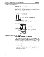
DIP Switch Settings
Set the NT11 operation status with the DIP switches located in the bottom
right corner on the rear side of the body.
DIP Switch Settings
Factory setting: ALL OFF
Emergency transfer mode: When power to the NT11 is turned ON with DIP
switch pin 3 turned ON, data transfer mode will be
entered directly without any other operation.
!Caution
In addition to the DIP switches, set also the “Comm. Method”, “Host Link
Speed”, “Automatic Reset”, etc. at the memory switches. For these settings,
refer to
3-7 Setting the Conditions of Communications with the PLC by Using
the Memory Switches
(page 71).
!Caution
After changing the switch settings, always press the reset switch or turn the
power off and back on.
Otherwise the system will not operate as expected.
!Caution
Confirm system safety before turning the power ON/OFF or resetting.
Otherwise the system may operate unpredictably.
Correct Use
Use the “System program erase” function only when changing the system
program.
It the system program is erased, it will not be possible to use the functions of
the NT11 unless another system program is transferred.
DIP Switch Pin
Function
SW1
1
RS-422A terminating resistance used
0
Not used
SW2
1
Screen data forced initialize effective
0
Ineffective
SW3
1
Emergency transfer mode
0
Ineffective
SW4
1
Switching to the System Menu disabled
0
Enabled
SW5
Reserved.
SW6
1
System program erase enabled
0
Disabled
Содержание NT11 - 01-2004
Страница 1: ...USER S MANUAL Cat No V084 E1 01 NT11 Programmable Terminal ...
Страница 2: ...NT11 Programmable Terminal User s Manual Produced January 2004 ...
Страница 3: ...iv ...
Страница 5: ...vi ...
Страница 13: ...xiv Safety Precautions 3 ...
Страница 27: ...14 Before Operating Section 1 6 ...
Страница 71: ...58 Connecting a Printer Section 2 8 ...
Страница 119: ...106 Daily Report Display History Printing Function Section 4 10 ...
Страница 157: ...144 Inspection and Cleaning Section 6 3 ...
Страница 162: ...149 Appendix B Dimensions Body NT11 SF121 B EV1 38 2 7 5 218 203 113 98 ...
Страница 163: ...150 Dimensions Appendix B ...
Страница 165: ...152 Transporting and Storing the NT11 Appendix C ...
Страница 183: ...170 Revision History ...
Страница 186: ...NT11 Programmable Terminal Cat No V084 E1 01 USER S MANUAL ...


