


93
Areas for Control/Notification
Section 4-3
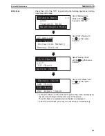
• Content upgrade memory table entry (refer to page 126)
The number of the numeral memory table entry is written to the word when
the numeral memory table entry contents change due to the System keys
operation on the NT11.
The contents of the word to which the numeral memory table entry has been
allocated also change.
As the number of the numeral table entry is written, the PT status numeral set-
ting strobe flag is simultaneously set ON (1). After this is notified to the PLC,
this flag reverts to OFF (0). Checking the status of this flag will provide a sim-
ple method of checking if a number has been input from the NT11.
Note that this function is not available with the character-string memory table.
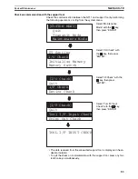
• PT status (refer to page 132)
The NT11 operation status and other information are written with the ON
or OFF of the bits as shown below.
The PT status control area (PLC to PT) can be allocated to the following PLC
areas.
Words Allocated of the PT
Status Notify Area
Words can be allocated for the PT status notify area (PT
®
host) in the follow-
ing host (PLC) areas.
*1 LR 00000 to LR 00199 are converted to CIO 01000 to CIO 01199.
Screen switching strobe
Password input error flag
15 14 13 12 11 10 9 8 Bit
PT status notify bits
0 0 0 0
Word m+2
PT operation status (1 (ON): RUN / 0 (OFF): STOP)
Numeral setting strobe flag
Symbol
C-series PLCs
Allocation
CV-series PLCs
Allocation
CS/CJ-series PLCs
Allocation
None
IR Area
OK
CIO Area
OK
CIO Area
OK
H
HR Area
OK
---
---
HR Area
Not for Host
Link
A
AR Area
OK
Auxiliary Area
No
AR Area
OK
L
LR Area
OK
---
---
LR Area
*1
Not for Host
Link
T
TC Area,
Timer PVs
No
Timer Area,
Timer PVs
No
TC Area,
Timer PVs
No
TU
---
---
---
---
TC Area,
Timer Completion Flags
No
C
TC Area,
Counter PVs
No
Counter Area,
Counter PVs
No
TC Area,
Counter PVs
No
CU
---
---
---
---
TC Area,
Counter Completion Flags
No
W
---
---
---
---
WR Area
Not for Host
Link
TK
---
---
---
---
Task Flags
No
D
DM Area
OK
DM Area
OK
DM Area
OK
E
EM Area
*2
,
current bank
OK
EM Area,
current bank
Not for Host
Link
EM Area,
current bank
Not for Host
Link
E0_ to
EC_
---
---
---
---
EM Area,
EM banks 0 to C
Not for Host
Link
Содержание NT11 - 01-2004
Страница 1: ...USER S MANUAL Cat No V084 E1 01 NT11 Programmable Terminal ...
Страница 2: ...NT11 Programmable Terminal User s Manual Produced January 2004 ...
Страница 3: ...iv ...
Страница 5: ...vi ...
Страница 13: ...xiv Safety Precautions 3 ...
Страница 27: ...14 Before Operating Section 1 6 ...
Страница 71: ...58 Connecting a Printer Section 2 8 ...
Страница 119: ...106 Daily Report Display History Printing Function Section 4 10 ...
Страница 157: ...144 Inspection and Cleaning Section 6 3 ...
Страница 162: ...149 Appendix B Dimensions Body NT11 SF121 B EV1 38 2 7 5 218 203 113 98 ...
Страница 163: ...150 Dimensions Appendix B ...
Страница 165: ...152 Transporting and Storing the NT11 Appendix C ...
Страница 183: ...170 Revision History ...
Страница 186: ...NT11 Programmable Terminal Cat No V084 E1 01 USER S MANUAL ...


