


13
Type
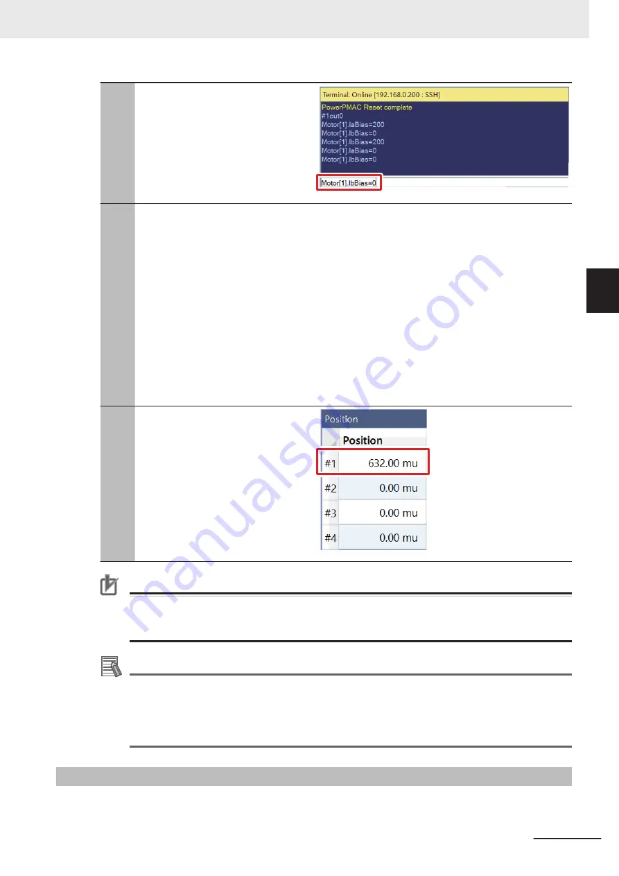
Motor[1].IaBias=0
and
Motor[1].IbBias=0
in the Terminal to
return the phase A and B bias currents
to 0.
14
If the
Motor[1].PhasePos
value de-
creases when values in step 10 and 12
are compared, set the sign of
Motor[1].PhaseOffset
to + (addition); if
the value increases, set the sign to −
(subtraction).
•
Since the value decreases in this ex-
ample, set
Motor[1].PhaseOffset=683
in the
global definitions.pmh.
If a sign of
Motor[1].PhaseOffset
needs to be changed, change the
sign in the global definitions.pmh and
perform download again following the
procedure in step 3 through 6.
15
Manually rotate the coupling that con-
nects the motor to encoder and check
that the desired scale is applied to the
current position in the Position window.
•
The
EncTable[1].ScaleFactor
value
is set to 8000 counts per rotation in
this example, so 8000 mu is added to
the current position per rotation.
Precautions for Correct Use
If the
save
command is not successfully completed, the transferred project is not saved in the
Controller. If the power to the Controller is switched OFF without the project being saved, the
transferred project is destroyed.
Additional Information
To change the counting direction of the digital quadrature encoder (clockwise/counterclock-
wise), change the sign of the following set values to write in the global definitions.pmh in step 2
to − (subtraction).
• EncTable[1].ScaleFactor
• Motor[1].PhasePosSf
3-4-1
Notes List
The following table shows details on notes (description of set items) in step 2.
3 DirectPWM Interface Connection Procedure
3-13
CK3M-series Startup Guide DirectPWM Interface (O047)
3-4 V
arious Controller Settings
3
3-4-1
Notes List


