EN-10
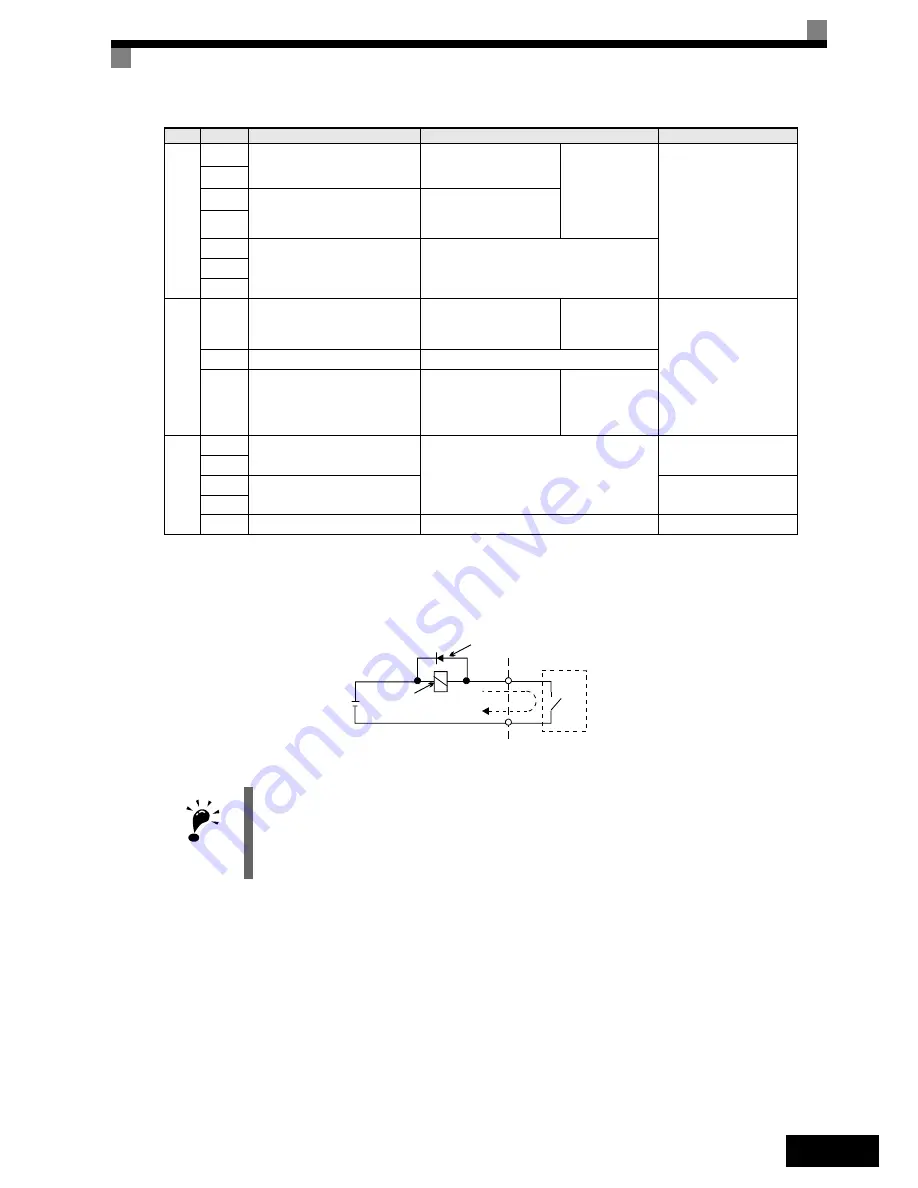
Fig 6 Flywheel Diode Connection
Digital out
put signals
M1
During run
(1NO contact)
Closed during Run
Function
selected by H2-
01 and H2-02
Relay contacts
Contact capacity:
1 A max. at 250 VAC
1 A max. at 30 VDC
*3
M2
M3
Zero speed
(1NO contact)
CLOSED when output
frequency at zero level
(b2-01) or below
M4
MA
Fault output signal
CLOSED across MA and MC during
faults
OPEN across MB and MC during faults
MB
MC
a
nalog output
signals
FM
Output frequency
Analog output fre-
quency signal;
0 to 10 V; 10V=FMAX
Function
selected by
H4-01
0 to +10 V max. ±5%
2 mA max.
AC
Analog common
–
AM
Inverter output power
Analog output power
signal;
0 to 10V; 10V=max.
appl. motor capacity
Function
selected by
H4-04
RS-485/
42
2
R+
MEMOBUS communications
input
For 2-wire RS-485, short R+ and S+ as
well as R- and S-.
Differential input, PHC
isolation
R-
S+
MEMOBUS communications
output
Differential input, PHC
isolation
S-
IG
Signal common
–
–
*1. The default settings are given for terminals S3 to S7. For a 3-wire sequence, the default settings are a 3-wire sequence for S5, multi-
step speed setting
1 for S6 and multi-step speed setting 2 for S7.
*2. Do not use this power supply for supplying any external equipment.
*3.
When driving a reactive load, such as a relay coil with DC power supply, always insert a flywheel diode as shown in
Fig 6
IMPORTANT
1. In
Fig 4
the wiring of the digital inputs S1 to S7 is shown for the connection of contacts or NPN transis-
tors (0V common and sinking mode). This is the default setting.
For the connection of PNP transistors or for using a 24V external power supply, refer to
Table 3
.
2. A DC reactor is an option only for Inverters of 18.5 kW or less. Remove the short circuit bar when con-
necting a DC reactor.
Type
No.
Signal Name
Function
Signal Level
External power:
30 VDC max.
Coil
Flywheel diode
1 A max.
The rating of the flywheel diode must
be at least as high as the circuit volt-
age.


