3 Check and start operation
3-1 The name and function for the operation and display
BU150R
37
3
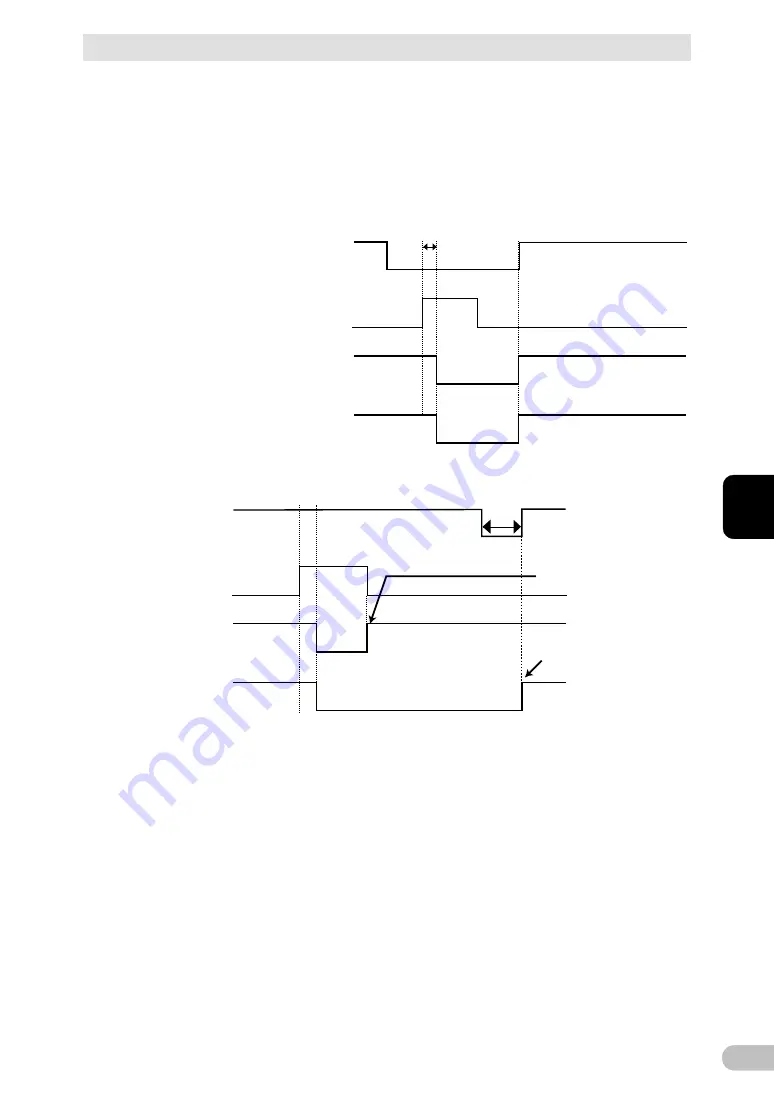
* "Setting" switch 4 is valid when the auto startup after recovery from power failure setting
("Setting" switch 2) is set to OFF (auto restart is performed).
* This setting mode is valid only after the UPS has been stopped by the contact signal
backup stop signal (BS).
* When a cable is connected to the RS232C port and the UPS monitoring software is
used, the unit operates in Mode A regardless of this setting.
1) When BS signal is used to stop the UPS after a power failure occurs.
2) When BS signal is used to shut down the UPS when AC input is ON
*1 For 10 seconds as a default setting.
AC input
Power output
(Setting switch 4 OFF:
Mode A)
Power output
(Setting switch 4 ON:
Mode B)
ON
OFF
ON
OFF
ON
OFF
ON
OFF
BS signal
*1
1 sec
AC input
Power output
(Setting switch 4 OFF:
Mode A)
Power output
(Setting switch 4 ON:
Mode B)
BS signal
*1
Starts up when BS signal
turns OFF
Starts up whenAC input
turns from OFF to ON
ON
OFF
ON
OFF
ON
OFF
ON
OFF
Содержание BU150R
Страница 22: ...2 Installation and connection 2 1 Installation BU150R 22 Incorrect Positions...
Страница 92: ...7 How to use option cards 7 3 SNMP Web card BU150R 92 7 3 SNMP Web card LAN 10 100...
Страница 101: ...10 References 10 2 Dimensions BU150R 101 10 10 2 Dimensions Unit mm Tolerance 2mm BU150R 438 480 87...
Страница 102: ...10 References 10 2 Dimensions BU150R 102 Stand for vertical layput 200 200 70 50 70 50...
Страница 103: ...10 References 10 2 Dimensions BU150R 103 10 Rubber feet 23 25 405 50 40 358 40 3...
Страница 104: ...10 References 10 2 Dimensions BU150R 104 Using Ear brackets 44 5 22 0 13 5 455 25 465...


