1-18
CT PC Box Parts
Auto Power Reset
1-, 2-, 3-Cell Color Touch Installation and Service Guide
/67-2014 Rev G
© 2011 Omnicell, Inc.
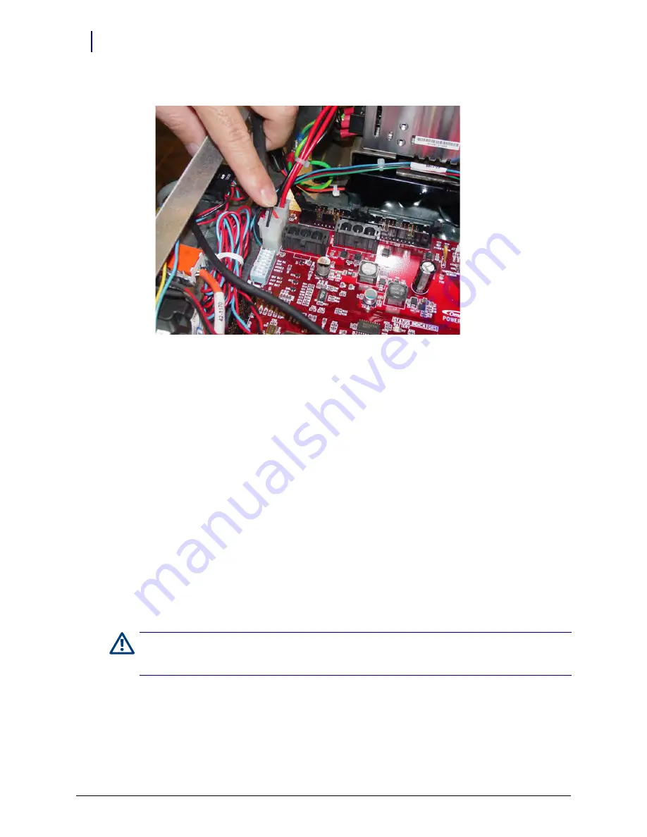
3. Locate the cable to the battery and insert the connector into the PowerCom3 board at J2.
Figure 1-25.
Connect the Battery Cable to J2 of the PowerCom3 Board
Installation Procedure
1. Remove the
CT PC Box from the shipping box and lift it onto the rail slides of the
cabinet. Do not slide the CT PC Box completely into the cabinet.
2. Thread the SPC cable into the CT PC Box and connect it to J12 and J13 of PowerCom3 board.
3. Replace the cover and lock it using the cam lock key #2036.
4. Slide the CT PC Box completely into the cabinet.
5. Pull open the keyboard door to access the screws fastening the CT PC Box to the frame.
6. Replace the buttonhead 8-32 x 7/8” and buttonhead 8-32 x 3/8” screws.
Auto Power Reset
When a power outage occurs, the power switch on the back of the PC box must be pushed to turn
the unit back on. In a hospital with multiple auxiliary cabinets, this is an unmanageable situation.
To solve the problem, change the dip-switch setting on the internal power/communication board
so the unit automatically turns on when the power is restored. The new settings should be a
production default in the future.
1. Open the PC box.
2. Change dip switches 1 and 2 on the power/communication board to
On
.
3. Close the PC box.
Caution:
Cabinets that have the new dip switch settings must be unplugged before doing maintenance as
the power switch will no longer turn off the power. A warning sticker for this situation should be placed on the
cabinet in manufacturing.


