background image

3-19

Input Setup – Virtual Math Channel
Virtual math channels allow you to perform math functions on the data from 

two physical channels and store the calculated result as a virtual channel. Up to 

16 virtual channels can be configured.

Standalone Operation

3

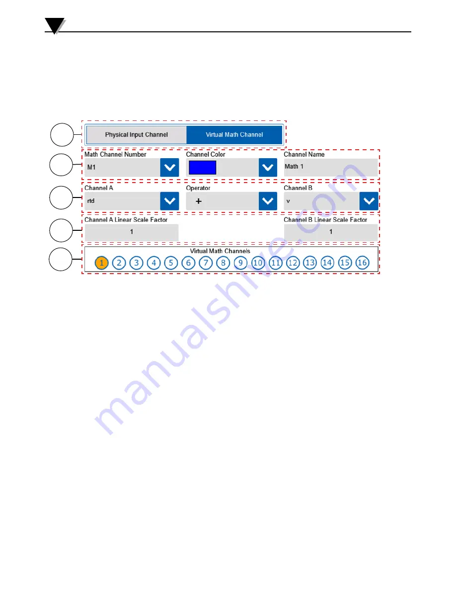
Figure 3-22 Input Type - Virtual Math

2

1

3

4

5

1.  Channel Type Buttons 

Allows selection of either a real physical input channel or a virtual Math 

channel.

2.  Math Channel Settings 

Selects the channel number, color and name to assign to the new math channel.

3.  Channel Operations 

Selects the two physical channels and math operation to perform.

4.  Scaling Factors 

Multiplies the channel value by the selected scale factor before performing the 

math operation to the two channels. The scaling factor can be either whole or 

decimal numbers.

5.  Channel Map 

The channel map provides a visual indication of the previously configured 

channels (shown in blue) and the currently selected channel (shown in orange).

Содержание OM-DAQXL-1 Series

Страница 1: ...e mail info omega com For latest product manuals www omegamanual info TM Shop online at omega com User sGuide OM DAQXL Multi Channel Universal Input Touch Screen Data Logger...

Страница 2: ...lter specifications without notice Servicing North America U S A Omega Engineering Inc Toll Free 1 800 826 6342 USA Canada only Customer Service 1 800 622 2378 USA Canada only Engineering Service 1 80...

Страница 3: ...2 6 2 6 1 1 Thermocouples 2 6 2 6 1 2 Voltage Wiring 2 6 2 6 1 3 Current Wiring 2 7 2 6 2 Three and Four Wire Sensors 2 7 2 6 2 1 Two Wire RTD Wiring 2 7 2 6 2 2 Three Wire RTD Wiring 2 8 2 6 2 3 Fou...

Страница 4: ...24 External Trigger Events 3 25 3 3 5 Data Session Settings 3 26 3 3 6 Alarm Settings 3 27 Main Alarm Screen 3 27 Alarm Status 3 27 Alarm Table 3 27 Alarm Toolbar 3 28 Add Edit Alarm Screen 3 29 3 3...

Страница 5: ...View 2 2 Figure 2 3 OM DAQXL Back View 2 3 Figure 2 4 OM DAQXL Left Side View 2 3 Figure 2 5 OM DAQXL Right Side View 2 4 Figure 2 6 OM DAQXL Top View 2 4 Figure 2 7 OM DAQXL Bottom View 2 4 OM DAQXL...

Страница 6: ...3 Inserting USB Accessories 2 11 Figure 2 24 Status LED Locations 2 12 Figure 2 25 Removing Battery Door 2 13 Figure 2 26 Connecting Battery 2 13 Figure 3 1 Login Window 3 1 Figure 3 2 Home Screen 3 2...

Страница 7: ...0 Figure 3 37 Display Options Screen 3 31 Figure 3 38 Communication Setting Ethernet 3 32 Figure 3 39 Communication Setting Wi Fi 3 33 Figure 3 40 Device Settings Diagnostics Screen 3 34 Figure 3 41 U...

Страница 8: ...nvironments Never operate with a power source other than the one recommended in this manual or listed on product labels This device has been designed for dry moisture free applications only Do not ope...

Страница 9: ...No Logging is performed No Trigger conditions are set 2 Armed Mode In this mode the device measures and displays configured analog digital inputs A Start Trigger condition is set No Logging is perform...

Страница 10: ...ent Verify the model number shown on the rear label of your data logger matches what was ordered Hardware 2 Model Specifications OM DAQXL 1 8 channel data logger with USB Host Device OM DAQXL 2 16 cha...

Страница 11: ...tton The touch screen display is used to display all measured data settings configuration menus and status information The three status LEDs provide visible indications of power battery charging statu...

Страница 12: ...nting bracket See Section 2 5 for information on how to wall mount the device The battery compartment door is also located on the back of the device See Section 2 11 for information on how to replace...

Страница 13: ...ort is present on the right side of the data logger 6 5 6 27 Hardware 2 Figure 2 7 OM DAQXL Bottom View Figure 2 5 OM DAQXL Right Side View ETHERNET PORT USB HOST PORT SHELL GROUND TERMINAL USB DEVICE...

Страница 14: ...nputs and communication interfaces Next while holding the device with one hand gripping the top of the device use the other hand to pry one of the bottom corners of the rubber boot outward and downwar...

Страница 15: ...lls and mV output pressure transducers require excitation voltage which is provided on channels 1 and 2 3 and 4 9 and 10 11 and 12 only See tables 2 3 and 2 4 for wiring information 2 6 1 Two wire sen...

Страница 16: ...between the negative leads of the two assigned channels as shown in figure 2 13 Hardware 2 Figure 2 12 DC Current Wiring Example External Excitation Sensor Type Odd Channel Even Channel Temperature 2...

Страница 17: ...l of the next consecutive even channel 2 6 2 3 Four Wire RTD Wiring For 4 wire RTD sensors the data logger performs a Kelvin resistance measurement using 1 channel to supply excitation voltage and the...

Страница 18: ...iring For bridge based sensors excitation voltage is supplied on channels 1 3 9 and 11 The next consecutive even channels must be used to measure the sensor output Bridge based sensor inputs are only...

Страница 19: ...corresponding pins on the data logger connector Hardware 2 Signal Name Pin Wire Color Digital Input 1 1 White Digital Input 2 2 Red Digital Input 3 3 Orange Digital Input 4 4 Purple Digital Output 1...

Страница 20: ...on with a PC using the supplied USB cable There is also a USB host port which allows external USB memory to be used for data storage USB Memory up to 64GB in size can be used with the data logger The...

Страница 21: ...he different LED indications Hardware 2 Figure 2 24 Status LED Locations Led Status Color and State 1 Power Charging DC Adapter Battery Connected Charged Green Connected Charging Green Flashing Not co...

Страница 22: ...he battery pack 1 Remove the four screws securing the battery door using the included screw driver 2 Remove the battery from the compartment 3 Plug the keyed connector on the end of the battery leads...

Страница 23: ...the appropriate plug for the outlet type in your country or region 1 Plug the AC cord into the AC adapter 2 Connect the DC output plug of the adapter into the OM DAQXL power port 3 Plug the AC cord in...

Страница 24: ...tored It also facilitates easy review and analysis of previously recorded data without the need of a laptop or PC 3 1 Login Window When the OM DAQXL first boots up the user is greeted with the login w...

Страница 25: ...p on this icon will invoke a fly out menu 3 System Clock Displays the current date and time 4 Data Logging Mode Status Shows the current logging mode Free running armed or logging 5 Alarm Status Shows...

Страница 26: ...reezes the current display and allows the user the ability to make annotations on the display using the stylus A screenshot will then be saved showing the annotation 4 Screen Shot Takes a screenshot o...

Страница 27: ...ide show Select channel group or Assign channels to groups Shows a tabular list of all currently configured channels Allows access to all stored data files for reviewing or copying Select the type of...

Страница 28: ...annel button on the toolbar to navigate to the Input Type screen There are two types of channels which can be configured physical input channels and virtual math channels Depending on the type of chan...

Страница 29: ...physical and math channel input types Temperature inputs are physical input channels 2 Input Type Settings For temperature inputs there are multiple sensor types available These include thermocouple R...

Страница 30: ...ion 3 3 1 Channel Type Button The channel type selects between physical and math channel input types Strain gage inputs are physical input channels 2 Input Type Settings For strain gage inputs there a...

Страница 31: ...will be applied to measurements across the full range of input 5 Moving Average Filter This setting provides the option to average an individual channels input samples 6 Graph Range The graph range is...

Страница 32: ...hannel input types Voltage inputs are physical input channels 2 Input Type Settings For voltage inputs there no sensor types or sub types available Only 1 channel is required per voltage input A chann...

Страница 33: ...isplay Range The display range boxes show the full range in engineering units for the voltage input being configured The graph range can be any subset of this range 4 Zero Adjust The zero adjust provi...

Страница 34: ...nt resistor must be installed across the input terminal A channel number color and name must be assigned for each channel 3 Channel Map The channel map provides a quick view of which channels have alr...

Страница 35: ...ansducer output that is a subset of the standard ranges to the display range 3 Display Range The display range boxes show the full range in engineering units for the current input being configured The...

Страница 36: ...between physical and math channel input types Frequency inputs are physical input channels 2 Input Type Settings For digital inputs there are 3 different sensor types to choose from The frequency typ...

Страница 37: ...This is a subset of the display range This determines what portion of the full display range will be shown initially in the waveform views This range can also be adjusted from the waveform view 5 Dec...

Страница 38: ...what will be shown in the data display area for a given input value 4 Zero Adjust This allows for a single offset value to be entered which will be applied to all readings in terms of the selected eng...

Страница 39: ...ype button The channel type selects between physical and math channel input types Frequency inputs are physical input channels 2 Input Type Settings For digital inputs there are 3 different sensor typ...

Страница 40: ...ntered which will be applied to all readings in terms of the selected engineering units 5 Graph Range This is a subset of the display range This determines what portion of the full display range will...

Страница 41: ...et time to be entered as well The reset time is the period after which you wish to have the counter reset back to zero 3 Channel Map The channel map provides a quick view of which channels have alread...

Страница 42: ...channel or a virtual Math channel 2 Math Channel Settings Selects the channel number color and name to assign to the new math channel 3 Channel Operations Selects the two physical channels and math o...

Страница 43: ...ull range of input 4 Moving Average Filter This setting provides the option to average an individual channels input samples 5 Graph Range The graph range is the y axis range that will be shown on the...

Страница 44: ...channels and their values for each of the settings in the table header 3 Back The back button returns to the Home Screen 4 Channel Groups This button navigates to the Select Channels screen where cha...

Страница 45: ...he home screen toolbar Trigger events can be used to start and stop a data logging session It is even possible to trigger multiple sessions using repeat trigger events Start and stop trigger events ca...

Страница 46: ...fore logging commences in HH MM SS format 2 Logging Duration The logging during determines how long the logging session continues in HH MM SS 3 Repeat Trigger Events If repeat trigger events are enabl...

Страница 47: ...atically re arm itself after the logging session ends A stop trigger event must be configured for this to occur Alarm Output Trigger Events The Alarm output option allows any of the alarms currently c...

Страница 48: ...n Options These options determine when a logging session is triggered by the external trigger input For the high and low options a trigger event is generated immediately if the trigger condition is me...

Страница 49: ...the log file If set to Average all of the data samples taken over the logging interval are averaged and the average value is saved to the log file 4 External 24V Excitation This selection turns on th...

Страница 50: ...creen Main Alarm Screen The main alarm screen shows all of the currently configured alarms in a table format From this screen you can perform various task including adding new alarms editing existing...

Страница 51: ...Enables any alarms currently selected in the alarm table Alarms must be enabled before their settings become active and will generate an alarm 5 Disable Disables any alarms currently selected in the a...

Страница 52: ...ce between the alarm threshold value and the value at which the alarm will be deactivated It is always in the same engineering units as the channel for which the alarm is being configured 5 Alarm Outp...

Страница 53: ...gure 3 36 General Settings Screen 3 3 7 Device Settings The device settings are five different screens which allow you to configure the way your device looks and works in addition to setting the date...

Страница 54: ...d Grid Color These options set the background color for the menu screens and the grid color for the Waveform views 3 Brightness This slider sets the display brightness Using a reduce brightness can in...

Страница 55: ...server protocol that automatically provides an Internet Protocol IP host with its IP address and other related configuration information such as the subnet mask and default gateway 3 IP Address If DH...

Страница 56: ...work This dropdown selection will show all of the WiFi networks within range 8 Security Key Enter the passphrase or security key for the selected network If it is an open network leave this field blan...

Страница 57: ...ormation This table shows the progress of each test as it is being run as well as the status and result of the test Standalone Operation 3 Figure 3 40 Device Settings Diagnostics Screen Diagnostics Th...

Страница 58: ...ns to the General settings screen of the device settings 4 Add User This button navigates to the Add User screen to allow a new user account to be created 5 Change Password This button navigates to th...

Страница 59: ...for the new user account Passwords must be between 4 and 10 characters in length 4 Confirm Password Re enter the password for the new user account It must match the password entered in the previous fi...

Страница 60: ...user account Password must be between 4 to 10 characters in length 2 Confirm Password Enter the same password as the previous field 3 Submit Submit and save the new password 4 Cancel Return to the Use...

Страница 61: ...website by visiting www omega com ftp and navigating to the OM DAQXL folder under Data Acquisition folder Standalone Operation 3 Figure 3 44 About Screen 1 Model Number Shows the model number of your...

Страница 62: ...ropriate button Then press the Upgrade button on the toolbar to begin the firmware upgrade process The progress will be indicated on the progress bar The device will reset itself to complete the firmw...

Страница 63: ...tion 3 Figure 3 47 Display Channel Fly Out Menu Figure 3 48 Views Fly Out Menu The Display Channels button fly out menu allows you to select which group of channels you would like to display and also...

Страница 64: ...can be assigned to multiple groups Standalone Operation 3 1 Group Selection These buttons let you select one group at a time to assign channels to 2 Channel Selection All currently configured channels...

Страница 65: ...ltiple channels visible these values will be for the currently selected channel 3 Channel Trace Shows the waveform for each input channel in the selected color 4 Scale Selector Shows the current time...

Страница 66: ...nnels can be displayed on the right third of the display area The graph scales can be adjusted using the scale selector in the same way as in the waveform view Standalone Operation 3 1 Channel Number...

Страница 67: ...s the average value of the data for each channel 5 Minimum This column indicate the minimum value of the data for each channel 6 Maximum This column indicates the maximum value of the data for each ch...

Страница 68: ...Four Channel Digital View 2 3 1 Channel Display A single tap on any of the four digital displays will switch the display mode to show a single channel display for that channel 2 Channel Number and Ch...

Страница 69: ...e The annotate button allows the user to freeze the current display and make annotations using the stylus Then a screenshot including the annotation can be saved in the directory configured in the dat...

Страница 70: ...ssing the red Log Data button or revert to the free running mode by pressing the white Free running button 3 5 3 Logging Mode In the logging the OM DAQXL will save data from all configured channels to...

Страница 71: ...tly logged in user are stored 4 Back Returns to the home screen 5 Storage Invokes a fly out menu that allows you to select which memory type to browse If you select a memory type not present a pop up...

Страница 72: ...ent directory 3 Back Returns to the stored files directory list 4 Storage Not selectable in the stored files list view 5 Review Opens the selected file in the review screen Depending on the size of th...

Страница 73: ...ch cursor location Tapping on a channel name will show the corresponding channels data values at each cursor location on the top of the graph 4 Page indicator Shows the current page displayed and the...

Страница 74: ...which channels you would like to view on the waveform graph Pressing the Display Channels button on the data review screen toolbar will take you to the review mode channel list screen where you can s...

Страница 75: ...4 1 NOTES 4...

Страница 76: ...al lines and terminal connections Connections must be free of corrosion Signal lines should be undamaged and free of sharp bends and twists Signal paths should avoid potential sources of noise high vo...

Страница 77: ...ns listed here in this manual If your OM DAQXL system requires service or calibration please call our Customer Service Department at 1 800 622 2378 or 203 359 1660 They will assist you in arranging th...

Страница 78: ...75 X 2 42 Weight 3 2 lbs 1 45 kg Power Supply AC Adapter Input 100 to 240 Vac 50 to 60 Hz 1 5 A max AC Adapter Output 12 Vdc 5A max Battery Lithium Ion Rechargeable 7 2 V 4800 mAh Battery Life Approxi...

Страница 79: ...to 1000 C 328 to 1832 F N 100 to 1300 C 148 to 2372 F R 0 to 1760 C 32 to 3200 F 0 15 of reading 2 0 C S 0 to 1760 C 32 to 3200 F B 500 to 1820 C 932 to 3308 F C 0 to 2315 C 32 to 4200 F U W U U W U...

Страница 80: ...s sec 1 s sec 12 s min 6 s min 2 s min 1 s min 12 s hr 6 s hr 2 s hr 1 s hr For All Channels Logging Mode Interval average Trigger Conditions Start Stop Timer date and time weekday and time alarm outp...

Страница 81: ...rnal PC communications Protocol Modbus TCP IP 7 5 External I O Alarm Outputs 4 open collector alarm outputs rated for 0 5A 30 Vdc with audible alarm buzzer Digital Outputs 4 open collector digital out...

Страница 82: ...7 5 7 6 Dimensions Dimensions mm inch Specifications 7 EVISIONS ECN DATE DR CHK ENG Note Ethernet port is only present on EW models 61 4 2 42 222 8 75 M4 INSERT SCREW 146 5 75...

Страница 83: ...the OM DAQXL it is recommended to pass the thermocouple through the supplied ferrite 2 turns before connecting it to the device When communicating with the OM DAQXL via Ethernet it is recommended to...

Страница 84: ...A if the unit is found to be defective it will be repaired or replaced at no charge OMEGA s WARRANTY does not apply to defects resulting from any action of the purchaser including but not limited to m...

Страница 85: ...s M U Turbine Paddlewheel Systems M U Totalizers Batch Controllers pH CONDUCTIVITY M U pH Electrodes Testers Accessories M U Benchtop Laboratory Meters M U Controllers Calibrators Simulators Pumps M U...

Отзывы: