18
Configuration Using LVCN414-SW software
(continued)
Step Three
USB
®
FOB INTERFACE
LVU700 series communicates with LVCN414-SW through a USB
®
interface called a Fob (LVU500-USB).
Before plugging your Fob into your computer’s USB
®
port, be sure that you have installed LVCN414-SW (see
omega.com/ftp
) on your computer.
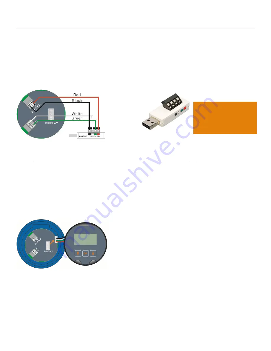
Connect the red, green, white and black wires from LVU700 series into the correct terminals on the Fob.
Tighten the screws on the terminals. Plug your Fob into the USB
®
port of your computer.
Wiring to Fob (LVU500-USB)
LVU500-USB
®
Fob
Wiring is identical for all LVU700 series – Use only the Red, Black, Green and White wires.
The
maximum cable distance
between the computer and LVU700 series is
15’
. This only applies for
configuring the LVU700 series.
Once LVU700 series is configured and prior to installation, isolate the white and green terminals from
active power to prevent a short from the configuration circuit.
Note:
When using the Fob, do not add VDC or VAC power. The Fob, when connected to the computer, will
provide the required power to the LVU700 series.
Note:
When connecting the sensor to the LVCN414-SW software, you must remove the display or the
software will not connect. Once completed, you can re-connect the display to the terminal.
Note:
Only use the
LVU500-USB
Fob (white).
The LVCN414-USB Fob
(black)
will not work
with
the LVU700 series.
Содержание LVU-700
Страница 1: ...1...
Страница 2: ...2...
Страница 6: ...6 Introduction continued Step One DIMENSIONS Dimensions for LVU706 Series Dimensions for LVU712 Series...
Страница 51: ...51...
Страница 52: ...52...


