6
MANUTENZIONE
E REGOLAZIONI
MAINTENANCE
AND ADJUSTMENT
18
OMCA S.r.l
-
Via Curiel, 6 - 42025 - Cavriago (RE) - ITALY
Telefono:
+39 0522 943502 / +39 0522 943503 -
Website
: www.omcasrl.it -
6.1
6.1 SOSTITUZIONE INSERTI
6.1 INSERTS REPLACEMENT
ATTENTION:
MAKE THIS OPERATION wITH CARE BECAUSE THE INSERTS
ARE SHARP.
BEFORE PERFORMINg THIS OPERATION, CAREFULLY READ
CHAPTER
6
,
MAINTENANCE AND ADJUSTMENTS
.
ATTENZIONE:
QUESTA OPERAZIONE DEVE ESSERE SVOLTA CON ATTENZIONE
IN QUANTO gLI INSERTI SONO TAgLIENTI.
PRIMA DI EFFETTUARE QUESTA OPERAZIONE, LEggERE
ATTENTAMENTE QUANTO INDICATO NEL CAPITOLO
6
MANUTENZIONI E REgOLAZIONI
.
1)
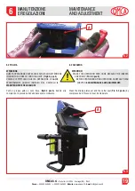
togliere il gruppo guide (
Fig.6.1 pos.A
), per eseguire questa
operazione occorre rimuovere le
4
viti (
2
per parte) (
Fig.6.1
pos.B
) poste sui fianchi della macchina, in corrispondenza del
nonio graduato.
ATTENZIONE: durante la rimozione delle viti,
tenere stretto il gruppo guide evitando che possa cadere
.
1)
Remove the driving plates set (
Pic. 6.1 pos. A
). To perform this
operation, remove the
4
screws (
2
for each side of the machine)
(
Pic. 6.1 pos. B
) where the nonius is.
ATTENTION:
when removing
the screws, hold the driving plates set to prevent them from
falling
.
2)
A questo punto (come indicato in
Fig.6.2
) la fresa è completamente
accessibile:
Per modello 760
-
760-M:
- allentare i grani di bloccaggio degli inserti (
Fig.6.2 pos.A
);
- rimuovere gli inserti e pulire accuratamente la loro sede;
- inserire l’inserto nella apposita sede con il nuovo lato tagliente
rivolto verso l’esterno;
- fissare l’inserto, stringendo delicatamente il grano di fissaggio;
- al termine stringere tutti i grani che fissano gli inserti.
Per modello 760/3F - 760/3F-M:
- togliere la vite di fissaggio degli inserti (
Fig.6.2 pos.A
);
- rimuovere gli inserti e pulire accuratamente la loro sede;
- inserire l’inserto nella apposita sede con il nuovo lato tagliente
rivolto verso l’esterno e stringere con l’apposita vite di
fissaggio;
Ogni inserto è composto da 4 lati taglienti, sostituirlo quando sono
stati utilizzati tutti i lati.
A
B
2)
At this stage the cutter is completely accessible (as showed in
Pic. 6.2
):
For model 760
-
760-M version:
- loosen the screws of inserts (
Pic. 6.2 pos. A
);
- remove inserts and accurately clean their seat;
- place the insert in its seat with the new cutting side facing
outward;
- fix the insert, gently tightening the screw;
- at the end, tighten all screws fixing the inserts.
For model 760/3F - 760/3F-M version:
- remove the screw of inserts (
Pic. 6.2 pos. A
);
- remove inserts and accurately clean their seat;
- place the insert in its seat with the new cutting side facing
outward, and tighten the screw;
Every insert consists in 4 cutting sides and has to be replaced when
all sides have been used.


