background image

49

5 Menu operations and functions

 5.4  Operations in the PDF file display screen (RX only)

Menu items and functions

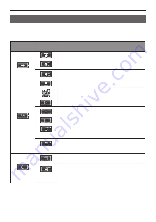
On the menu on which the PDF file is displayed, you can work with that PDF file as shown below.

*: Initial default

PDF main 

menu

PDF

submenu

Available settings

MOVE PDF
DOCUMENT

*

Displays the top page

Displays the previous page

Pressing the [BRT] lever toward [

] gives you the same effect.

Displays the next page

Pressing the [BRT] lever toward [

] gives you the same effect.

Displays the last page

Displays your desired page

EXPAND/
SHRINK PDF 
DOCUMENT

Displays the whole page

*

Displays the page to fit width

Displays the page to fit height

Zooms in the page

Pressing the [ZOOM] lever toward [T] gives you the same ef-
fect.

Zooms out the page

Pressing the [ZOOM] lever toward [W] gives you the same ef-
fect.

ROTATE PDF 
DOCUMENT

Rotates the page counterclockwise

Rotates all other pages in the document.

Rotates the page clockwise

Rotates all other pages in the document.
Pressing the [MEAS/ENTER] joystick gives you the same ef-
fect.

Содержание IPLEX IV9420RT

Страница 1: ...INSTRUCTIONS INDUSTRIAL VIDEOSCOPE IPLEX RX series IPLEX RT series IV9620RX IV9635RX IV9650RX IV9675RX IV9420RX IV9435RX IV9620RT IV9635RT IV9650RT IV9675RT IV9420RT IV9435RT ...

Страница 2: ...8 48 Woerd Avenue Waltham MA 02453 U S A Telephone 1 781 419 3900 L43 Office Tower Langham Place 8 Argyle Street Mongkok Kowloon Hong Kong Telephone 852 2481 7812 Wendenstrasse 14 18 20097 Hamburg Germany Telephone 49 40 23 77 30 Telephone 61 130 013 2992 3 Acacia Place Notting Hill VIC 3168 Australia ...

Страница 3: ... Preparing the power supply 13 3 2 Pre operation preparation 15 Attaching the optical adapter 15 Turning on power 16 Selecting the optical adapter 16 Checking the remaining battery level 17 Checking lighting of illumination at the insertion tube s distal end 18 Checking the angulation operation of the insertion tube 18 Attaching the USB flash drive 19 Setting up the main unit and performing observ...

Страница 4: ...e screens 48 Menu display and functions 48 5 4 Operations in the PDF file display screen RX only 49 Menu items and functions 49 6 Stereo measurement procedures RX stereo measurement function only 51 6 1 Measurement Flow 52 6 2 Attaching the stereo optical adapter 53 6 3 Registering the new stereo optical adapter or re registering the stereo optical adapter 54 Registering the new stereo optical ada...

Страница 5: ...es 71 Common problems 72 8 2 Requesting repair of this product 74 9 Specifications 75 9 1 Operating environment 75 9 2 Other specifications 75 External application standard 78 Software license information 78 9 3 Optical adapter specifications 79 For 4 mm type insertion tube 79 For 6 mm type insertion tube 79 Appendix 80 System chart 80 ...

Страница 6: ...iv ...

Страница 7: ... with options and separately available items not only creates the risk of abnormal operation it also can damage the product Expanded functions of the IPLEX RX RT series The IPLEX RX RT series functions can be expanded IPLEX RT IPLEX RX IPLEX RX IPLEX RX Stereo measurement function Contact Olympus for details Important Information Please Read Before Use Marks used in this manual The following signa...

Страница 8: ... observation object etc or the insertion tube may touch the object resulting in electric shock Before stowing the instrument in its carrying case be sure to turn off power and remove the battery Leaving the battery loaded during storage can cause it to become hot causing the risk of fire Do not use this instrument in any environment including strongly radioactive environments that does not conform...

Страница 9: ...rved image may be whitish caused by the illumination light or a part of the view field may be lacked The optical adapter may fall off the insertion tube s distal end if used in this condition In this case immediately stop the inspection care fully withdraw the insertion tube and secure the optical adapter as described in Attaching the optical adapter P 15 Tip adapter not properly attached The stro...

Страница 10: ...o not open or close covers caps in an area subject to high humidity and or dust Close covers caps before storing the instrument and when they are not in use Note the following precautions whenever removing the instrument from its carrying case Do not apply undue force when pulling the insertion tube from the slot in the cushion When removing the control unit or the main unit do not lift it up by t...

Страница 11: ... in a closed automobile in the sun near a heater etc Fluid leaking from the battery can cause loss of sight if it gets into your eyes Flush your eyes with tap water or other clean water without rubbing Contact a physician immediately Do not use the battery charger outdoors Otherwise electric shock might occur or smoke emission and fire might occur causing dam age to the charger The battery charger...

Страница 12: ...le spare batteries is recommended when long hours of battery powered operation are expected The battery charging time is normally about two hours and 30 minutes generally speaking Recommended temperature range for Li ion battery operation Discharging using main unit 10 C to 40 C Charging 0 C to 45 C Storage 20 C to 60 C Using the battery under a temperature outside the above temperature ranges wil...

Страница 13: ...he safety ratings cautions and serial number are on stickers on parts of the main unit and the control unit If labels are missing or if their contents are illegible contact Olympus Model name serial number Caution Rating Main unit Control unit Caution both sides Caution Caution both sides ...

Страница 14: ...lid of the carrying case for in structions on how to pack the instrument in the carrying case Name Count IPLEX RX or RT main unit 1 USB flash drive for recording images 1 AC adapter 1 AC power cord 1 VGA conversion cable 1 Optical adapter case 1 Shoulder strap 1 Optical adapter case holder 1 Lens cleaning kit cotton swab brush 1 Tip cap either for 4 mm or for 6 mm 1 Stopper 1 Name Count Insertion ...

Страница 15: ... unit 9 Strap holder 10 Strap bracket 11 Front panel 12 Universal cable 13 Optical adapter case holder 14 Ring 15 Shoulder strap No Name 16 Control unit holder 17 AC adapter connector cap 18 LIGHT button 19 POWER button 20 Tripod screw hole 21 Battery cover 22 Lock release lever 23 Scope handset holder 24 Lock release button 25 Video connector cap 2 3 5 6 7 8 9 10 11 12 13 14 15 4 1 Main unit 16 1...

Страница 16: ...surement operations RX Stereo measurement function only 4 VIEW button Retrieve screen display thumbnail screen display 5 Grip 6 BRT lever Adjusting the brightness 7 MENU EXIT button Menu display 8 Joystick guard No Name 9 FRZ REC button Freeze record observed image two locations left and right 10 ZOOM lever Zooming the image 11 Hanger To hang the control unit on the main unit 12 Insertion tube hol...

Страница 17: ... 1 Optical adapter positioning cut surface 7 O ring 2 First screw thread 8 Illumination 3 Second screw thread 9 Product abbreviation 4 Connecting screw thread 10 Positioning pin 5 Objective lens 11 Product name abbreviation and serial number 6 Nut For information about the product abbreviation see 9 3 Optical adapter specifications P 79 Forward view Forward view Side view Side view Stereo optical ...

Страница 18: ...ge indicator 16 Thumbnail selection frame 17 Folder name 18 File name 19 PDF indicator RX only 20 Remaining media capacity 21 Adapter name RX only 22 Measurement indicator RX ste reo measurement function only The displayed title is the title that was entered on the Live screen the last time the system was used Should you notice any dirt stains or other abnormalities on the LCD monitor see 7 Storag...

Страница 19: ... turned off before performing pre observation and pre operation preparation and inspection 3 1 Pre observation preparation Preparing the power supply When using the battery See P 13 When using the AC adapter See P 14 1 CAUTION Preparing the power supply Using the battery Removing the battery Slide the lock release lever to the side to open the battery cover Noting the orientation of the battery in...

Страница 20: ...er connector cap After connecting the provided AC power cord to the AC inlet of the AC adapter plug the plug end of the AC power cord securely into a 3P power outlet If you find it difficult to remove the battery hook your finger directly onto the battery to remove it AC inlet AC adapter connector cap ...

Страница 21: ...nto the distal end 6 mm type 4 mm type Be sure to attach the O ring to the insertion tube s distal end before using the optical adapter Water getting into the area where the insertion tube and optical adapter join might cause malfunction or damage Also note that an optical adapter by itself is not watertight If an optical adapter cannot be mounted or removed because the nut will not turn stop usin...

Страница 22: ...n using the stereo optical adapter see 6 3 Registering the new stereo optical adapter or re register ing the stereo optical adapter P 54 When using AT100S NF IV94 or AT100S FF IV94 selecting 100SN or 100SF from the optical adapter list enables to display the erect image NOTE 2 Turn the optical adapter nut clockwise until the first screw thread passes over the con necting screw thread 3 Once past t...

Страница 23: ...power about 1 to 2 Charge the battery replace with a charged battery or connect the AC adapter 1 Do not record or delete images and do not format the USB flash drive If power runs out during these operations data could be corrupted 2 Should the battery indicator start to flash immediately turn off power or connect the AC adapter Continued use of the instrument will result in it shutting down which...

Страница 24: ...optical adapter etc Turning ON the power will light the illumination automatically The light intensity is adjusted depending on the brightness of the observation object The light indicator at the bottom right of the LCD monitor also is displayed Extend the insertion tube straight out and operate the ANGLE joystick to check for smooth angulation section operation Angulation movement matches the ang...

Страница 25: ... a flat surface for observation use the handle as a stand Adjust the handle to an angle that allows the LCD monitor to be easily viewed The angle of the handle can be adjusted smoothly to any position within the range shown in the figure above Observation can be done with the main unit set up on a flat surface hung from something or on a tripod The USB flash drive can be removed by moving the ejec...

Страница 26: ...d with the platform installed at an angle may cause the main unit to fall off You can use a square platform that measures 45 mm or less from the center of the tripod screw Hang the main unit Set up the main unit on a tripod When hanging the main unit to do observation hook an S hook string or other item onto the handle Attach the tripod platform to the main unit to use a tripod to do observations ...

Страница 27: ...o the two belt brackets and one of the two belt holders 2 Adjust the length of the shoulder strap by the length adjuster buckle and ad just the screen to an easy to view angle 3 Hang the shoulder strap on your shoulder and do observations 1 Attach the shoulder strap hooks to the two belt brackets 2 Adjust the length of the shoulder strap by the length adjuster buckle 3 Hang the shoulder strap on y...

Страница 28: ...til you feel a click Pull the control unit straight upward from the main unit When the control unit is affixed to the back of the main unit hold down the center of the lock release button as you pull upwards Detaching the control unit When putting down the main unit while the control unit is attached to it always place it on its side or base Do not use excessive force or twist the control unit whe...

Страница 29: ...etween the handle and the main unit Walking with the control unit attached to the main unit back left side When carrying the control unit fixed to the main unit be careful for followings Hold the handle of the main unit Take care not tot tilt or swing the main unit This instrument may be damaged Universal cable ...

Страница 30: ...with the insertion tube fastening belt near the insert tube bend stopper Transport the instrument by holding the main unit or by hanging it from the strap 1 Pass the Hook Loop fastener of the optical adapter case holder through the ring on the shoulder strap 2 Fold the Hook Loop fastener over to fasten it as shown in the diagram Stow the instrument in its carrying case when moving or transporting ...

Страница 31: ... material buttons joysticks or levers Irregularities such as cuts or kinks in the universal ca ble Insertion tube angulation section distal end Any looseness in materials other than the angulation section Replacement required Contact Olympus Any dirt or water droplets on the objective lens of the distal end Continued use in this condition creates the risk of damage to the optical adapter and or di...

Страница 32: ... only When the stereo optical adapter is registered Before and after measurement See 6 5 Check ing measurement values P 58 Check the serial number on the optical adapter selection screen when the stereo optical adapter is attached to the main unit RX stereo measurement function only See 6 Stereo measurement procedures RX stereo measure ment function only P 51 LCDmonitor Any surface cracks or other...

Страница 33: ...pushing force twisting or tension to the insertion tube 4 Lock the angulation section angle and direction angulation lock and perform observation When the angulation section is at the desired angle and direction remove the stopper and raise the ANGLE LOCK lever The angulation angle can be adjusted finely even though the angulation is locked 5 While watching the display screen carefully withdraw th...

Страница 34: ...achieve under low temperatures The image noise may be extreme under high ambient temperatures In case of RX a yellow temperature indicator is displayed when ambient temperature is about 80 C to warn you that it is approaching the upper limit Note that this indicates that the upper limit of the ambient operating temperature is being approached Should the following message appears while inspecting w...

Страница 35: ...larging an image Zoom Freezing an image that contains high speed action may result in a blurred image Images are zoomed using digital zoom As a result the image may become slightly coarse at higher zoom factors When using the stereo optical adapter with RX there are some restrictions in operations For details refer to Observing measurement area P 60 and Measuring the distance to the measurement ar...

Страница 36: ...under certain observation conditions Brightness adjustment with the BRT lever The BRT lever can be used to adjust brightness by changing the overall brightness of a live im age during observation While a live image is displayed press the BRT lever on the control unit toward to brighten the overall image or toward to darken it Displaying a high sensitivity image monochrome boost The live image beco...

Страница 37: ...der from the live screen 1 While a live image is displayed move the MEAS ENTER joystick left right up and down The folder name shown in the upper left area of the screen changes The folder that is displayed is the folder for the image being recorded or played back The folder configuration which can be switched with the MEAS ENTER joystick is up to the second layer NOTE ...

Страница 38: ... live screen freeze screen P 41 To record the date time title logo measurement results and other on screen information onto the image being recorded press the MENU EXIT button while a live screen is displayed On the menu that appears select RECORD PRINT SCREEN ON OFF and set ON See P 42 Setting ON in the FILE NAME MARK menu enables following functions when recording images Function to select recor...

Страница 39: ...names Use this function to categorize image files The category names of the file marks can be changed Contact Olympus for details NOTE 1 Select the folder of the save destination See 4 3 Switching the folder from the live screen P 31 for details about operations 2 While a live image is displayed short press the FRZ REC button This freezes the image 3 While the freeze screen is displayed long press...

Страница 40: ...lect MODIFY change the folder of the save destination and short press the MEAS ENTER joystick 6 Select the strings in the preset title list registered in advance and short press the MEAS ENTER joystick This records the still image The screen shows STILL during recording a still image The screen goes black for a moment and then the frozen image is displayed Setting OFF in the FILE NAME MARK menu en...

Страница 41: ...ing the VIEW button stops movie recording and displays the retrieve screen long pressing the VIEW button stops movie recording and displays the thumbnail screen NOTE 4 Select the mark to add to the end of the file name of the image you are record ing short press the MEAS ENTER joystick 5 Select the strings in the preset title list registered in advance and short press the MEAS ENTER joystick After...

Страница 42: ...image 3 Switch the image you want to play back Use the MEAS ENTER joystick to switch the image you want to play back MEAS ENTER joystick left operation Scrolls from the currently displayed image to the image chronologically before it When images are sorted in descending order performing this operation when at the last im age will return to the first image MEAS ENTER joystick right operation Scroll...

Страница 43: ... up down left or right to move the selection boundary around the screen The thumbnail where the selection boundary is located is the currently selected image To play back an image Select the image you want to play back and then short press the MEAS ENTER joystick This starts full screen view playback of the selected image To select multiple images to move or delete them Selecting an image and then...

Страница 44: ... the PDF file you want to display and push the MEAS ENTER joystick The PDF file will be displayed You can display a PDF file on the Live or Freeze screen Use alphanumeric characters or symbols to name the PDF file Otherwise you are not able to display the PDF file Pressing the VIEW button held down for a short time allows you to switch over between the PDF file and the Live or Freeze screen When t...

Страница 45: ...site http www olympus ims com en service and support downloads 4 8 Using recorded images on a PC The live image can be displayed on the external monitor by connecting the provided VGA conver sion cable connected to the video output connector of the main unit to the VGA cable commercially available connected to the external monitor commercially available 4 7 Displaying live images on an external mo...

Страница 46: ...xecute 3 Press the MEAS ENTER joystick to apply the setting and return to the previous screen 5 1 Performing menu operations 5 Menu operations and functions Pressing the MENU EXIT button while doing menu operations returns to the previous screen Pressing the LIVE GAIN button while doing menu operations returns to the live screen NOTE Main menu Sub menu ...

Страница 47: ...newly creating a folder for image re cording and playback Switches the folder for recording and playing back the image changes the folder name and creates the folder The default is 100IV7R1 Switches to the folder displayed on the menu screen For operations to switch to the folder which is not displayed on the menu screen see 4 3 Switching the folder from the live screen RECORD FILE NAME MARK Lette...

Страница 48: ...TER Optical adapter selecting Specifies an optical adapter When using the stereo optical adapter with RX see 6 2 Attaching the stereo optical adapter P 53 SELECT PDF FILE RX only PDF file selection Selects PDF files stored in the PDF folder on the USB flash drive so that they can be viewed See 5 4 Operations in the PDF file display screen RX only P 49 for details about operations IMAGE MODE RX onl...

Страница 49: ...used to specify the type of information to be displayed ALL Show the date time title OLYMPUS logo optical adapter name zoom level and brightness level DATE TIME LOGO Show the date time title and OLYM PUS logo DATE TIME Show the date time and title OFF Hide information BEEP ON OFF Specifies whether to sound the beep Specifies whether beep tones sound from the built in speak ers ON Sound OFF Do not ...

Страница 50: ...ters select CLEAR and then press the MEAS ENTER joystick To input a space Move the cursor to the location where you want to input the space select SPACE and then press the MEAS ENTER joystick 3 Select EXECUTE and then press the MEAS ENTER joystick This displays the title you input on the LCD monitor Main menu Sub menu Available settings SETUP STEREO ADAPTER IM AGE DISPLAY MODE Sets the screen in m...

Страница 51: ...ng a character string as a preset title P 45 1 1 2 2 3 3 The preset title list has five pages To change pages select the text string in line 1 or line 10 of the currently displayed page and then tilt the MEAS ENTER joystick upwards or downwards Registering a character string as a preset title After you register commonly used character strings to favorites you can recall them when you are inputting...

Страница 52: ...elete a preset title by performing the registration operation while the title input box is blank 4 Press MEAS ENTER joystick towards the left This closes the preset title list screen Adjusting image sharpness RX only The sharpness of the image can be emphasized The saturation of the image can be adjusted IMAGE MODE SHARPNESS IMAGE MODE SATURATION Pressing the MEAS ENTER joystick toward right or le...

Страница 53: ...rocedure below to configure date and time settings Be sure to set the correct date and time before using the instrument for the first time Date and time information is shown on the display and is also recorded on the print screen Data recording is also performed in accordance with date and time information Selecting a language displays the message to let you know that the process is being performe...

Страница 54: ... displayed on the menu screen see 4 3 Switching the folder from the live screen COPY FILE Copy image files to folder Thumbnail screen only Copies recorded images to a different folder The currently selected image or all images that are check marked on the thumbnail screen are copied MOVE FILE Move image files to folder Thumbnail screen only Moves recorded images to a different folder The currently...

Страница 55: ...next page Pressing the BRT lever toward gives you the same effect Displays the last page Displays your desired page EXPAND SHRINK PDF DOCUMENT Displays the whole page Displays the page to fit width Displays the page to fit height Zooms in the page Pressing the ZOOM lever toward T gives you the same ef fect Zooms out the page Pressing the ZOOM lever toward W gives you the same ef fect ROTATE PDF DO...

Страница 56: ...cal horizontal and scroll bars on the PDF screen ON Display OFF Hide SPLIT SCREEN ON OFF Allows you to split and display the PDF screen and live or freeze screen However the split mode will be terminated when you start up a spot ranging screen or measurement screen You can switch over between the PDF screen and the live or freeze screen by pressing the VIEW button held down for a short time ON Spl...

Страница 57: ...ghtness Olympus cannot guarantee the ac curacy of measurement results We recommended that users identify the measurement accuracy through experiments This measurement method identifies a pair of corresponding points on the left image and the right image same location obtained by using two objective lenses that are set in parallax If the corre sponding points cannot be identified properly the corre...

Страница 58: ...pter or re registering the stereo optical adapter See P 54 Selecting the registered stereo optical adapter See P 57 Attaching the stereo optical adapter See P 53 Checking measurement values before measurement See P 58 Checking measurement values after measurement See P 58 Make sure that the measurement values obtained when Checking measurement values before measurement and when Checking measuremen...

Страница 59: ...d without dirt or dust If the attached optical adapter rattles or is loose or even though it does not rattle or is not loose if it is not firmly attached completely by rotating in the direction of arrow A shown in the picture the measurement accuracy deteriorates After installation of the optical adapter if the distal end is handled by grasping the optical adapter it may turn in the opposite direc...

Страница 60: ...stration is an operation to create the information for the combination of your stereo optical adapter and the insertion tube The information that is created is stored in the internal memory of the main unit 2 Select SELECT OPTICAL ADAPTER in Menu Operation and select NEW STEREO ADAPTER Then press the MEAS ENTER joystick 1 Attach the stereo optical adapter to the insertion tube s distal end See 6 2...

Страница 61: ...adapter P 53 for details about operations 6 Adjust the brightness of a white image Use the check tool provided with the stereo optical adapter Insert the distal end of the insertion tube into the forward view guide hole or the side view guide hole until it touches the end Rotate the check tool to adjust the direction so that the protrusion in the center of the white indented part comes close to th...

Страница 62: ...section so that no force is applied to the optical adapter and angulation section 8 The following message is displayed Remove the optical data media USB flash drive from the USB connector and then select OK and press the MEAS ENTER joystick Remove the optical data media Keep the optical data media USB flash drive in the optical adapter case so it does not get lost 9 Check measurement values After ...

Страница 63: ...r is displayed 3 Confirm that Serial No is matched with Serial number of the stereo optical adapter Select OK and press the MEAS ENTER joystick The live image is displayed in the monocular view type or the binocular view type 4 Check measurement values After the stereo optical adapter is selected the measurement values must be checked See 6 5 Checking measurement values P 58 for details about oper...

Страница 64: ...ER joystick to specify the measurement points 2 points See Measurement P 63 for details about operations The measurement accuracy may be reduced by loose attachment of the optical adapter or dirt on the lens components Confirm the measurement values after the stereo optical adapter is regis tered selected or before and after measurement 1 Insert the insertion tube s distal end into the optical ada...

Страница 65: ... after measurement and make sure that both measurement values are almost identical If the measurement results differ significantly from each other check that the optical adapter is not loose and the lens is not dirty and if required re register the stereo optical adapter see 6 3 Registering the new stereo optical adapter or re registering the stereo optical adapter P 54 If the optical adapter is l...

Страница 66: ... the shadow area on the measurement area move or rotate the position of the insertion tube to change the direction or the distance for capturing images And use the BRT lever to adjust to the slightly dark image To change the display mode see 5 2 Using the live screen freeze screen P 44 Restriction for monocular view type A part of the left image in the binocular view type is zoomed in Restriction ...

Страница 67: ...iction during spot ranging The zoom function cannot be used The gain mode cannot be switched Fixed to AUTO The sharpness adjustment cannot be switched Fixed to 1 The brightness adjustment range is from 1 to 7 The monochrome boost is not available NOTE In case of the monocular view type short press the MEAS ENTER joystick while displaying the live screen or the freeze screen or press the ZOOM lever...

Страница 68: ...higher Green Yellow Red To move the cursor tilt the MEAS ENTER joystick in the desired direction Moving the cursor Spot ranging screen Finishing the spot ranging Press the LIVE GAIN button or press the ZOOM lever toward T or W Short press the MEAS ENTER joystick The measurement screen is displayed Starting the measurement NOTE While checking the distance to the measurement area by using the spot r...

Страница 69: ...rement points or reference points specified in the left image area are displayed in the right image area Confirm that positions of measurement points or reference points in the left image area are same as positions of corresponding points in the right image area For details of screens see Measurement screen P 64 and for detail operations see Specifi cation of measurement points P 67 4 Record the m...

Страница 70: ... insertion tube s distal end to the specified measurement point is displayed The object distance mark is displayed in the following colors Up to 15 mm Green Recommended mea surement distance Up to 30 mm Yellow Possible measurement distance 30 mm and higher Red Cursor Specifies a mea surement point or reference point Point Indicates a speci fied measure ment point or reference point Displaying the ...

Страница 71: ...ment point or reference point specified immediately before ALL CLEAR Clears all specified measurement point or reference point METHOD Selects a measurement method See Measurement method types P 66 for details about operations UNIT Selects the units of the measurement result from mm or inch EXIT MEASUREMENT Exits the stereo measurement screen The display returns to the screen before measurement sta...

Страница 72: ...oints This mode allows for measuring the distance from a measurement point to the reference line de fined by two reference points Measurement method types Distance Point to line Distance Point to line This mode allows for measuring the distance from a measurement point to the reference plane de fined by three reference points It indicates depth and height Height is indicated by a positive value an...

Страница 73: ...ion Then press the MEAS ENTER joystick to specify the required number of measurement points for each measurement method in the left image area on the left side of the screen The measurement results and the object distance measured at the cursor distance between the distal end of the adapter and the measurement area are displayed In addition the measurement result displaying mm indicates that the c...

Страница 74: ...s very short Contact Olympus about changing the battery For details about how to load and remove the battery see Using the battery P 13 7 3 Cleaning components Clean the insertion tube immediately after withdrawing the insertion tube Leaving the insertion tube very dirty for long periods can cause it to become corroded Cleaning the insertion tube Dirt or other foreign matter on the insertion tube ...

Страница 75: ...Grasping the rigid portion of the distal end wipe the optical adapter Best results may be obtained using a commercially available absolute ethanol or isopropyl alcohol Dirt on the threads of the screws of the optical adapter Moisten a cotton swab with a commercially available absolute ethanol or isopropyl alcohol and continue cleaning until doing so leaves no dirt on the cotton swab Clean in the s...

Страница 76: ...he LCD monitor Do not use a cloth that is hard dirty or has foreign matter on it Doing so may damage the surface of the LCD monitor 7 4 Storage precautions Store this product under normal room temperature and humidity Never subject cables to severe bending pulling binding twisting or crushing forces Do not allow a cable to be exposed to heat which can melt its covering Otherwise cable might be dam...

Страница 77: ...nly images recorded with this instrument can be displayed RECORDING MEDIA ERROR PLEASE FORMAT THE RECORDING MEDIA The format of the USB flash drive cannot be recognized Format the USB flash drive on the instrument IMAGER ERROR PLEASE TURN OFF THE POWER The self check function activated and prompted termination of opera tion Stop inspection and turn the instrument off then on again OVER CURRENT USB...

Страница 78: ... tion tube The nut of the optical adapter is rotated in the wrong direction Reinstall using the correct procedure Attaching the optical adapter P 15 Message Cause and recommended action HIGH TEMPERATURE DISTAL END PLEASE IMMEDIATELY PULL OUT THE SCOPE The message prompts you to stop inspection because the self check function was triggered Immediately pull the insertion tube out of the observation ...

Страница 79: ...y adjust the external monitor The optical adapter is old Replace the optical adapter with a new one The optical adapter is loose Attach the optical adapter properly Attaching the optical adapter P 15 Color reproduction is poor The white balance is set improperly Re adjust white balance The image is noisy The automatic brightness control is set erroneously Perform the BRT lever operation to configu...

Страница 80: ...g the instrument Malfunctions that occur during the warranty period are done at no charge according to the warranty agreement Be sure to attach the warranty agreement when returning the instrument for repairs Repair will be charged if the warranty agreement is not attached The freight fees are paid by the user even if repairs are done free of charge Olympus will not repair an instrument contaminat...

Страница 81: ...hed The stereo measurement cannot be carried out underwater Other parts than above Water resistant proof construction Use in water is not supported The instrument is not water resistant if the battery cover and others are open Meeting operating environment specifications does not constitute any guarantee against damage to or malfunction of this equipment Use AC adapter and battery charger indoors ...

Страница 82: ...g LCD panel 6 5 inch TFT full color low reflective coating type Input Output connector USB connector A connector USB 2 0 compatible Power supply Battery Specified battery Lithium Ion Model Manufactured by INSPIRED ENERGY NC2040NO29 Nominal voltage 10 8 V DC Nominal capacity 31 Wh Battery powered operating time Approximately 120 minutes based on new battery For details refer to the instruction manu...

Страница 83: ... Distance from a point to a line reference line that is defined by indicating two points on the screen Depth Distance from a point to a plane that is defined by indicating three points on the screen Area Area of the plane that is defined by indicating multiple points on the screen Lines Length of the line connecting multiple points indicated on the screen Displaying and recording the measurement r...

Страница 84: ...Directive This mark indicates the environmental protection use period applicable to electronic infor mation products sold in China in accordance with the Management Methods for Control ling Pollution by Electronic Information Products of February 28 2006 and the Require ments Concerning Pollution Control Markings for Electronic Information Products Caution During the environmental protection use p...

Страница 85: ...ole when mounted on the insertion tube 3 Indicates the length of the rigid portion at the insertion tube s distal end when mounted Adapter name AT40D IV96 AT80D NF IV96 AT80D FF IV96 AT120D NF IV96 AT120D FF IV96 Product abbreviation 40D 80DN 80DF 120DN 120DF Character color Black Red Green Red Green Optical system Field of view 40 80 80 120 120 Direction of view Forward Forward Forward Forward Fo...

Страница 86: ... commercially available Shoulder strap Carrying case The LCD monitor is covered by a LCD protection sheet The distal end is covered with a tip cap 4 mm type RX IV9420RX IV9435RX 4 mm type RT IV9420RT IV9435RT 6 mm type RX IV9620RX IV9635RX IV9650RX IV9675RX 6 mm type RT IV9620RT IV9635RT IV9650RT IV9675RT RX RT main unit ...

Страница 87: ...harger optional USB flash drive for recording images 4 mm type AT80D FF IV94 AT120D NF IV94 AT120D FF IV94 AT120S NF IV94 AT120S FF IV94 AT50D 50D IV94 AT50S 50S IV94 6 mm type AT40D IV96 AT80D NF IV96 AT80D FF IV96 AT120D NF IV96 AT120D FF IV96 AT80S IV96 AT100S NF IV96 AT100S FF IV96 AT60D 60D IV96 AT60S 60S IV96 Optical adapter Rigid sleeve 4 mm type MAJ 1737 for IV94 6 mm type MAJ 1253 for IV9...

Страница 88: ......

Отзывы: