background image

Powering up and shutdown

 / Shutdown

IV.

 OPERATION INSTRUCTIONS

IV.  

1 - 2

Page

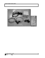
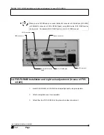
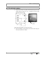
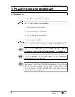
Front panel of FV5-LDPSU

1-2 Shutdown

When FV300, FV500 or FV1000 is used, close FV300, FV500 or FV1000 software.

1. 

Turn shutter switch (4) to CLOSE.

2. 

Turn key switch (3) left to OFF position.

3. 

Turn power switch (2) to O-(OFF) position.

4. 

In case that laser is not used for a long period of time, pull out power cord from

power consent.

5. 

Turn off the FV10-PSU and the UCB. (FV1000)

(3)

(2)

(4)

(1)

TIP

Содержание FV5-LD405

Страница 1: ...m performance of this system and also for safety considerations This manual contains six sections SAFETY GUIDE SYSTEM OUTLINE SPEC PACKING DETAILS CHECK OPERATING INSTRUCTIONS TROUBLESHOTTING and BACK...

Страница 2: ......

Страница 3: ...1 Page Caution 1 This manual part or whole shall not be used or reproduced without permission 2 Information in this manual is subject to change without notice...

Страница 4: ...MEASURES ACCORDING TO IEC60825 1 1993 A1 1997 A2 2001 LASER PRODUCT RADIATION SAFETY STANDARD I 4 1 II SYSTEMOUTLINE SPEC This section describes outline of the system and specifications 1 System outli...

Страница 5: ...D indicators IV 4 1 V TROUBLESHOOTING This section describes countermeasures to the troubles 1 Countermeasure when trouble occurs V 1 1 VI BACK PANEL SWITCH SETTINGS This section describes back panel...

Страница 6: ...the following book conventions Symbols for warning caution and hint used Conventions Description Indicates a warning to user to prevent injuries and or damage of products including peripheral furnitur...

Страница 7: ...sure before using the system System may not be guaranteed when it is used with other methods than described in this manual Unless instructions are observed more trouble may occur Please use this syst...

Страница 8: ......

Страница 9: ...tective housing label 2 4 3 Cautions when using the system 3 1 3 1 About system move 3 1 3 2 Caution when using 3 1 3 3 Caution 3 1 4 USER S SAFETY PROTECTION MEASURES ACCORDING TO IEC60825 1 1993 A1...

Страница 10: ......

Страница 11: ...refer to Chapter 4 USER S SAFETY PROTECTION MEASURES ACCORDING TO IEC60825 1 1993 A1 1997 A2 2001 LASER PRODUCT RADIATION SAFETY STANDARD and exercise adequate countermeasures and then use the laser p...

Страница 12: ...t path as the laser beam may come outside and it may enter your eye which is very dangerous z Do not set or remove the sample during laser emission laser scanning If you set or remove the sample in su...

Страница 13: ...OFF When using ether it is recommended that the room is well ventilated z Be careful so as not to apply any excessive force to connecting cord or cable as it is very weak against bend or twist z Do no...

Страница 14: ...ODUCT RADIATION SAFETY STANDARD When using remote interlock connector contact our local sales office for sure as it may cause electric shock or fire z See also instruction manual for microscope regard...

Страница 15: ...struction for sure When label is blurred or peeled off contact our local sales office and ask if new label for change is available 2 1 1 Warning label The warning label shown below is attached to the...

Страница 16: ...ached to the system Place attached In case of FV5 LD405 In case of FV5 LD405 Laser beam comes out here Aperture label is attached In case that you purchase our FV5 FUR405 our service personnel would a...

Страница 17: ...Warning label Label related to laser safety I SAFETY GUIDE I 2 3 Page In case of FV5 LD440 Opening label is attached...

Страница 18: ...tective housing label as shown below is attached to the system Place attached In case of FV5 LD405 In case that you purchase our FV5 FUR405 our service personnel would attach manipulator cover to it P...

Страница 19: ...40 Protective housing label may be attached to the place other than the place shown in this manual It is a warning label for our service personnel When label is blurred or peeled off contact our local...

Страница 20: ......

Страница 21: ...hen using FV5 LD405 only z Power cable is also used to stop power supply against unlikely event Power cable connector located at back panel of FV5 LDPSU or power consent should be within a reach of yo...

Страница 22: ......

Страница 23: ...e users of laser products to take proper safety protection measures summarized below When using this system be sure to take proper measures regarding the following points For details please refer to t...

Страница 24: ...315 2 C2 100 2 265 302 5 to 315 3 T2 10 x 10 min 98 5 sa 400 to 1400 4 C3 1 0 400 to 450 5 C3 100 02 450 450 to 600 5 C4 100 002 700 700 to 1050 6 C4 5 1050 to 1400 6 C5 10 1 4 b 400 to 106 7 C6 1 for...

Страница 25: ...If should be the laser safety officer s responsibility to review the following precautions and designate the appropriate controls to be implemented Wherever practicable laser protective enclosures sho...

Страница 26: ...access to other authorized persons if it is clearly evident that there is no optical radiation hazard at the time and point of entry 10 3 Key control Class 3B and Class 4 laser products not in use sho...

Страница 27: ...diffusely reflecting material of appropriate reflectivity and thermal properties or by absorbers Open laser beam paths should be located above or below eye level where practicable The beam paths of C...

Страница 28: ...focus the beam Reflecting surfaces that appear to be diffuse may actually reflect a considerable part of the radiation beam specularly especially in the infra red spectral range This may be potential...

Страница 29: ...wavelength e visible light transmission requirements f radiant exposure or irradiance at which damage to eyewear occurs g need for prescription glasses h comfort and ventilation i degradation or modif...

Страница 30: ...dent Where protective eyewear is required to cover a band of radiation the minimum value of O D measured within the band shall be quoted The value of O D required to give eye protection can be calcula...

Страница 31: ...stance Because of this hazard potential only persons who have received training to an appropriate level should be placed in control of such systems The training which may be given by the manufacturer...

Страница 32: ...ted with a full biophysical investigation of the circumstances under which the accident occurred c pre interim and post employment ophthalmic examinations of workers using Class 3B and Class 4 lasers...

Страница 33: ...violet transmitting tubing or mirrors such as quartz are used 11 2 2 Visible and intra red collateral radiation The visible and near infra red radiation emitted from flash tubes and pump sources and t...

Страница 34: ...urers he should make himself aware of the different degrees of risk and hazards associated with the processing of such materials and take appropriate precautions to prevent for example the emission of...

Страница 35: ...ls for each class The use of the classification system will in most cases preclude any requirement for radiometric measurements by the user The classification scheme relates specifically to the access...

Страница 36: ...erse elevation and pointing accuracy of the laser system and extends either to the limit of the NOHD or to the position of any target or backstop The exact NOHA will also depend on the nature of any m...

Страница 37: ...on laser product shall not permit human access to laser radiation in excess of the accessible emission limits of Class 1 or Class 2 as applicable NOTE Additional guidance can be found in IEC 60825 3 a...

Страница 38: ...should be terminated where possible at the end of its useful path by a material that is diffuse and of such a colour and reflectivity as to make beam positioning possible while still minimizing the r...

Страница 39: ...nvironment c Good room illumination is important in areas where laser eye protection is worn Light coloured diffuse wall surfaces help to achieve this condition d Fire thermally Induced aberrations in...

Страница 40: ......

Страница 41: ...s outline and specifications of this system We recommend that you use this system after reading this section and understanding this system Note for this section I II I S SY YS ST TE EM M O OU UT TL LI...

Страница 42: ......

Страница 43: ...1 1 1 1 System Outline 1 1 2 Specifications 2 1 2 1 Specifications of this system 2 1 3 Operating hours 3 1 3 1 Hour meter 3 1 Regarding DIP switches at back panel of FV5 LDPSU see V I 1 Warning to b...

Страница 44: ......

Страница 45: ...o that the system can suppress fluctuation of wavelength and power 3 Light stable laser output can be acquired with light feedback 4 This system can attain the function equivalent to AOTF even if conn...

Страница 46: ......

Страница 47: ...ype2 Mass 2 700g Fiber cable Kind Polarized preserved fiber cable FV5 FUR405 Fiber output Length Min 6mW Max 13mW when integrated with FV5 LD405 3m Environment conditions Indoor use Altitude up to 200...

Страница 48: ......

Страница 49: ...is being lighted The reset switch on the Hour meter panel is not be refreshed even if it is pushed HOUR METER INDICATES THE TIME IN SEVEN DIGITS AS FOLLOWS HHHHMM M MM M LOWER 3 DIGITS MINUTE IS DISPL...

Страница 50: ......

Страница 51: ...packing details of this system We recommend that you use this system after reading this section and checking the details of packing Note for this section I II II I P PA AC CK KI IN NG G D DE ET TA AI...

Страница 52: ......

Страница 53: ...n with FV5 LD440 1 2 1 4 LD Interface FV10 LDIF configuration for LD405 laser or LD440 laser in FV1000 system 1 2 1 4 1 LD405 configuration 1 2 1 4 2 LD440 Configuration 1 2 2 Packing details of this...

Страница 54: ......

Страница 55: ...This system can be integrated with FV5 COMB 2 for FV300 or FV500 FV5 COMB FV5 LDPSU FV5 LD405 FV5 SU or FV3 SU 3 FV COMB Cable LD LDPSU Inline Cable FV5 FUR405 FV5 COMB2 1 2 AOTF Combiner FV5 COMBA co...

Страница 56: ...B2 For connection details of FV300 or FV500 see instruction manual of FV300 or FV500 1 4 LD Interface FV10 LDIF configuration for LD405 laser or LD440 laser in FV1000 system 1 4 1 LD405 configuration...

Страница 57: ...head and semiconductor laser power supply unit 1 z BNC Cable the cable that connects semiconductor power supply with FV5 LCU Laser Control Unit for FV300 FV500 1000 FV5 LD405 2 FV5 LD405 SET When usi...

Страница 58: ...I PACKING DETAILS CHECK III 2 2 Page FV5 LDPSU FV5 LD405 FV5 LD440 BNC Cable For FV5 LD405 Manipulator cover For FV5 LD405 FV COMB Cable LD LDPSU In line Cable FV5 FUR405 For FV5 LD405 Power cord Cabl...

Страница 59: ...sure In case that LD LDPSU inline cable comes off from FV5 LDPSU FV5 LD405 becomes shaky and it would lead to breakage In addition if cable comes off during running time it would cause a failure 3 In...

Страница 60: ...ROI REX function can be used For details of ROI REX function refer to FV1000 manual 3 2 FV5 FUR405 Installation and Light axis adjustment In case of FV5 LD405 1 Install FV5 FUR405 to FV5 LD405 and ad...

Страница 61: ...e bottom of FV5 LD405 440 are provided Location of holes is shown in a figure unit mm It is possible to fix the base using 6 screws M3 of 12mm long or less Figure represents FV5 LD405 It is the same a...

Страница 62: ......

Страница 63: ...ER RA AT TI IO ON N I IN NS ST TR RU UC CT TI IO ON NS S This section describes operation of this system We request that you use this system after reading this section and understand the system Note f...

Страница 64: ......

Страница 65: ...er using FV300 or FV500 3 1 3 2 Laser emission area and Laser intensity change for AOTF combiner using FV300 or FV500 3 2 3 3 The way of changing the emission area ROI REX and intensity of Laser with...

Страница 66: ......

Страница 67: ...or FV1000 boot up FV300 FV500 or FV1000 software When you use the FV1000 at first you turn on the FV10 PSU and the UCB Next you turn on the FV5 LDPSU Last you run the FV10 ASW FV10 SW software In cas...

Страница 68: ...00 or FV1000 is used close FV300 FV500 or FV1000 software 1 Turn shutter switch 4 to CLOSE 2 Turn key switch 3 left to OFF position 3 Turn power switch 2 to O OFF position 4 In case that laser is not...

Страница 69: ...N laser would emit in continuous wave mode provided that the following conditions are satisfied z Interlock is short circuited z Power switch is turned to ON position z Key switch is ON z Shutter swit...

Страница 70: ...V5 LDPSU refer to VI 1 Back panel switch settings 2 2 When you wish to stop laser emission Even if shutter is OPEN laser emission would stop provided that any of the following conditions is satisfied...

Страница 71: ...y can be changed from FV300 or FV500 Laser intensity can be changed from 1 to 100 if the maximum value is set to 100 For further details see instruction manual for FV300 or FV500 1 Connect FV5 COMB 2...

Страница 72: ...1 to 100 if the maximum value is set to 100 1 Verify that FV5 COMBA is connected with FV5 LCU 2 Connect FV5 LCU with FV5 LDPSU 3 Set REX from FV300 or FV500 software 4 After REX setting start scannin...

Страница 73: ...from 1 to 100 if the maximum value is set to 100 1 Connect FV10 LDIF with FV5 LDPSU Type2 2 Set ROI REX from FV10 ASW FV10 SW software 3 After ROI REX setting start scanning so that laser emission are...

Страница 74: ......

Страница 75: ...ON LED is not lighting it indicates that laser is not emitted When you wish to emit laser see 2 1 When laser emits and satisfy the conditions required There is an exception that laser may not be emitt...

Страница 76: ......

Страница 77: ...s Before you contact our local sales office please read this section and try the countermeasures In case that the trouble occurs persistently then contact our local sales office Note for this section...

Страница 78: ......

Страница 79: ...CONTENTS 1 Countermeasure when trouble occurs 1 1 1 Laser does not emit 1 1 2 Laser power is weak 1 1 Regarding DIP switches at back panel of FV5 LDPSU see VI 1 Warning to back panel switch settings...

Страница 80: ......

Страница 81: ...on Key switch is not turned ON Turn it ON IV 1 1 Section Shutter is turned CLOSE Turn it to OPEN Even if you use FV300 FV500 or FV1000 and shutter switch is turned to CLOSE laser does not emit for saf...

Страница 82: ......

Страница 83: ...describes particularly important issue back panel switch settings Read this section before you use the system Note for this section V VI I B BA AC CK K P PA AN NE EL L S SW WI IT TC CH H S SE ET TT T...

Страница 84: ......

Страница 85: ...CONTENTS 1 Warning to back panel switch settings 1 1 1 1 Dip Switch Settings 1 1 1 2 Rotary Switch Settings 1 3...

Страница 86: ......

Страница 87: ...trolled with FV300 FV500 or FV1000 turn this switch to OFF position When shutter is controlled with FV300 orFV500 turn this switch to OFF position In FV1000 this switch should be ON not OFF When FV5 L...

Страница 88: ...sible In case that this system is connected with FV1000 set DIP switch 5 to ON position for sure If you use this system with DIP switch set to OFF position it is very dangerous as control from FV10 AS...

Страница 89: ...tch only Do not touch left side rotary switch If you change left rotary switch you may not be able to get optimum performance of this system When you use FV5 LD405 align arrow mark of right side rotar...

Страница 90: ......

Страница 91: ......

Страница 92: ...157 U S A OLYMPUSSINGAPOREPTELTD 491B River Valley Road 12 01 04 Valley Point Office Tower Singapore 248373 OLYMPUSUKLTD 2 8 Honduras Street London EC1Y OTX United Kingdom OLYMPUSAUSTRALIAPTY LTD 31 G...

Отзывы: