Olivetti d-Copia 4003MF Скачать руководство пользователя страница 377


1-5-93

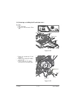
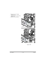
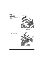
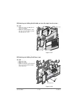
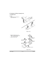
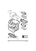
(14)Detaching and refitting the rear cover

Pocedure

1. Open the rear cover.

(50/60 ppm model only)

(1)Remove the screw and then the ground-

ing wire.

(2)Open the connector cover and then 

remove three connectors.

Figure 1-5-159

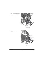
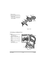
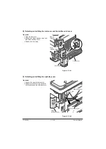
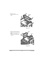
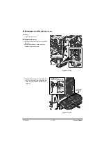
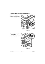
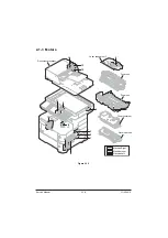
2. Remove the fulcrum axis by sliding the 

rear cover assembly while avoiding rear 
cover and then remove the rear cover 
assembly.

Figure 1-5-160

Connector cover

Connectors

Rear cover

Screw

Grounding wire

Rear cover 
assembly

Flucrum axis
(Rear cover assembly)

Rear cover

Service Manual

Y116

540-5

Содержание d-Copia 4003MF

Страница 1: ...SERVICE MANUAL Multifuction Digital Copier d Copia 4003MF d Copia 4004MF d Copia 4003MF Plus d Copia 4004MF Plus d Copia 5004MF d Copia 6004MF Code Y116540 5...

Страница 2: ...PUBLICATION ISSUED BY Olivetti S p A Gruppo Telecom Italia Via Jervis 77 10015 Ivrea TO Copyright 2015 Olivetti All rights reserved...

Страница 3: ...ill gal de jeter les batteries dans des eaux d gout municipales V rifiez avec les fonctionnaires municipaux de votre r gion pour les d tails concernant des d chets solides et une mise au rebut appropr...

Страница 4: ...Procedure in U207 1 3 44 Added Error codes 1 3 54 1 3 55 1 3 58 to 60 Changed Item number of original 1 3 55 to 57 Correction List of the Error Codes 1 3 62 Added a display of TDRS connection state 1...

Страница 5: ...cover left middle cover 2 2 16 Deleteed U326 U341 U343 U407 U429 U432 U470 2 3 1 2 3 2 Correction parts number in maintenance parts 2 3 3 Added cautions sentence 2 3 15 Correction main engine board co...

Страница 6: ...sonnel to ensure the safety of their customers their machines as well as themselves during maintenance activities Service personnel are advised to read this booklet carefully to familiarize themselves...

Страница 7: ...this symbol CAUTION Bodily injury or damage to property may result from insufficient attention to or incorrect com pliance with warning messages using this symbol Symbols The triangle symbol indicates...

Страница 8: ...or dusty place This may cause fire or electric shock Do not install the copier near a radiator heater other heat source or near flammable material This may cause fire Allow sufficient space around th...

Страница 9: ...carefully Always check that the copier is correctly connected to an outlet with a ground connection Check that the power cable covering is free of damage Check that the power plug is dust free If it i...

Страница 10: ...caution labels that should be present on the machine according to the instruction handbook are clean and not peeling Replace with new ones if necessary Handle greases and solvents with care by followi...

Страница 11: ...This page is intentionally left blank...

Страница 12: ...lling the IC card reader holder HyPAS model only 1 2 20 1 3 Maintenance Mode 1 3 1 Maintenance Mode 1 3 1 1 Executing a maintenance item 1 3 1 2 Maintenance modes item list 1 3 2 3 Contents of the mai...

Страница 13: ...ntirely black 1 4 76 3 Image is too light 1 4 77 4 The background is colored 1 4 79 5 White streaks are printed vertically 1 4 80 6 Black streaks appear longitudinally 1 4 81 7 Black or white streaks...

Страница 14: ...ching and refitting the primary paper feed unit and the pickup roller 1 5 5 1 2 Detaching and refitting the retard roller 1 5 5 2 MP tray paper feed section 1 5 7 2 1 Detaching and refitting the MP pa...

Страница 15: ...4 Detaching and refitting the right upper cover 1 5 86 5 Detaching and refitting the left upper cover 1 5 86 6 Detaching and refitting the center stay cover 1 5 87 7 Detaching and refitting the front...

Страница 16: ...2 46 1 Connector position 2 2 46 2 PWB photograph 2 2 46 3 Connector lists 2 2 47 4 Detaching and refitting the PWB PSPWB 2 2 48 2 2 7 Operation panel PWB OPPWB for HyPAS model 2 2 52 1 Connector posi...

Страница 17: ...Purpose Tray A4 A5 A6 B5 B6 Folio 216 340 mm Letter Legal Statement Exec utive Oficio II 16K ISO B5 Envelope 10 Envelope 9 Envelope 6 Envelope Monarch Envelope DL Envelope C5 Hagaki Oufuku hagaki You...

Страница 18: ...475 455 575 mm 18 11 16 17 15 16 23 1 4 475 455 590 mm Weight Not include toner container Basic model 47 4 lbs or less 21 5 kg or less HyPAS model 48 5 lbs or less 22 0 kg or less 51 4 lbs or less 23...

Страница 19: ...Original Feed System Fixed Item Description 40 ppm 50 ppm 60 ppm Printing Speed Same as Copy Speed First Print Time A4 feed from Cassette 9 0 seconds or less 8 0 seconds or less Excluding time for sy...

Страница 20: ...dpi 200 400 dpi 200 100 dpi File Format TIFF MMR JPEG compression JPEG PDF MMR JPEG compres sion XPS PDF A PDF high compression Scanning Speed 3 A4 landscape 300 dpi Image quality Text Photo original...

Страница 21: ...es 3 Original Tray 4 Original Eject Table 5 Inner Tray 6 Eject Paper stopper 7 Front Cover 8 Cassette1 9 Power Switch 10 Original Stopper Compartments 11 USB Memory Slot 12 Front Cover Open Button 13...

Страница 22: ...13 1 Option Interface Slot 2 Network Interface Connector 3 USB Interface Connector 4 Envelope Lever 5 Fuser Cover 6 MP Paper Guides 7 MP Sub Tray 8 MP Tray 9 Paper Length Guide 10 Paper Width Guide 1...

Страница 23: ...1 1 7 Figure 1 1 3 14 15 16 17 14 Toner Container 15 Toner Container Lock Lever 16 Registration roller 17 Waste Toner Box Service Manual Y116540 5...

Страница 24: ...1 1 8 3 Option Figure 1 1 4 1 2 3 4 5 6 7 1 Card Reader 2 Cassette 2 3 Cassette 3 4 Cassette 4 5 Cassette 5 6 Rear Tray 7 Eject Paper Stopper Service Manual Y116540 5...

Страница 25: ...Memory Indicator 10 Attention Indicator 11 Numeric keys 12 Clear key 13 Reset key 14 Start key 15 Stop key 16 Program key 17 Power Indication 18 Energy Saver key 19 Authentication Logout key 20 Status...

Страница 26: ...el key 3 Copy key 4 Send key 5 FAX key 6 LCD 7 System Menu Counter key 8 Numeric keys 9 Authentication Logout key 10 Clear key 11 Quick No Search key 12 Enter key 13 Energy Saver key 14 Reset key 15 S...

Страница 27: ...8 5 1 Cassette paper feed section 2 MP tray paper feed section 3 Conveying section 4 Image scanner section 5 Laser scanner section 6 Developer section 7 Toner container section 8 Drum section 9 Transf...

Страница 28: ...is available for the machine 1 PF 320 2 PT 320 50 60 ppm model only 3 Card Authentication Kit B 4 Expansion Memory 7 IB 50 9 Data Security Kit E 11 USB Keyboard 10 UG 33 6 HD 6 HD 7 8 IB 51 Software o...

Страница 29: ...r Avoid places subject to dust and vibrations Choose a surface capable of supporting the weight of the machine Place the machine on a level surface maximum allowance inclination 1 Avoid air borne subs...

Страница 30: ...Replace the operation panel sheet except 240V AC model Connecting the power code Clearing the counter maintanance item U927 Exit maintenance mode Setting of the fuser pressure release lever 40 ppm mo...

Страница 31: ...1 Hinge joints 2 Outer case 3 Upper front pad 4 Upper left pad 5 Upper right pad 6 Waste toner box 7 Power code 8 Operation guide etc 9 Plastic bag 10 Document tray 11 Main unit 12 Inner pad 13 Plasti...

Страница 32: ...fear of breakage Figure 1 2 3 Removed the packing components that a fixed tape and shock absorbing material etc are 1 A main unit is carried on a paper feeder Refer to the installation guide for the d...

Страница 33: ...over Figure 1 2 5 2 Rotate the toner container lock lever to the lock position and then the unlock position Figure 1 2 6 Setup of a toner container Release button Front cover Lock position Toner conta...

Страница 34: ...unit Figure 1 2 7 Caution Do not press too firmly on the center of the toner container or touch the toner feed slot or the terminal parts Figure 1 2 8 Toner container Main unit Terminal part Toner fe...

Страница 35: ...order to distribute the toner evenly inside the container Figure 1 2 9 5 Set the toner container to the main unit and then turn the toner container lock lever to the lock position 6 Close the front co...

Страница 36: ...located on the back side of the main unit 2 Connect the other end of the cable to the network router Connecting at USB 1 Connect the USB cable to the USB interface connector located on the back side...

Страница 37: ...1 2 13 Push the bottom plate down 40 ppm model only Figure 1 2 14 2 Push the lock lever on the right side guide and slide to the desired paper size Figure 1 2 15 Loading paper Cassette Main unit Botom...

Страница 38: ...ng to use appears in the cassette size window Figure 1 2 16 5 If you are going to set paper that is lon ger than A4 pull out the extension cas settes pushing the lock button one by one and adjust them...

Страница 39: ...nds alternately to create a gap and feed air between the papers 4 Finally align the papers on a level flat table If the paper is curled or folded straighten it before loading Paper that is curled or f...

Страница 40: ...o the operation panel sheet of the corresponding language 5 Refit all the removed parts Figure 1 2 21 Replace the operation panel sheet except 240V AC model Right operation lid Left operation lid Left...

Страница 41: ...rear cover 2 Remove the inlet cover 3 Connect the power cord to the main unit and the wall outlet 4 Refit the inlet cover 5 Close the rear cover Figure 1 2 23 Setting of the fuser pressure release le...

Страница 42: ...ed Product Library disc if you want to use the printer function of this machine or perform TWAIN WIA transmission from your PC Reference of an operation guide Perform the high altitude settings when a...

Страница 43: ...2 Select Country Code and enter a destination code using the numeric keys refer to the destination code list P 1 3 63 3 Press the start key Data initialization starts 4 Press the stop key to exit 1 E...

Страница 44: ...the upper interface cover and the lower interface cover Figure 1 2 26 3 Remove two screws and the Slot cover 4 Insert the SD card in the SD card slot 5 Refit all the removed parts Figure 1 2 27 Upper...

Страница 45: ...y rotating Figure 1 2 29 3 Insert the expansion memory into the memory socket so that the notches on the memory align with the correspond ing protrusions in the slot 4 Close the shield plate 5 Refit t...

Страница 46: ...d from the wall outlet Figure 1 2 31 4 Open the rear cover 5 Remove two interface covers from the main unit Figure 1 2 32 6 Remove two screws and the option slot cover Figure 1 2 33 OFF Indicator Powe...

Страница 47: ...9 Refit two interface covers 10 Close the rear cover Figure 1 2 35 11 Connect the plug of the power cord to a wall outlet 12 Turn the power switch on Figure 1 2 36 Screws SSD Option slot Rear cover Lo...

Страница 48: ...Supplied parts of IC card reader holder 10 1702P6UN1 Procedure 1 Mount the IC card reader to the IC card reader holder Figure 1 2 37 Parts Quantity Part No IC card reader holder 10 1 1702P6UN1 Parts Q...

Страница 49: ...3 Slide the left operation lid and then remove it 4 Remove the left operation panel cover and the left operation panel sheet 5 Remove the IC card reader cover Figure 1 2 39 Rib Rib IC card reder hold...

Страница 50: ...rew 8 Refit all the removed parts Figure 1 2 40 9 Affix a label on the ICcar reader cover aligning it with the positioning mark Figure 1 2 41 Screw IC card reader holder Operation panel assembly USB c...

Страница 51: ...in with admin istrator privileges 3 Press Next of Optional Function 4 Select CARD AUTHENTICATION KIT B and press Activate 5 The License Key entry screen is displayed Enter the License Key using the nu...

Страница 52: ...1 2 24 This page is intentionally left blank Service Manual Y116540 5...

Страница 53: ...the maintenance item number using the cursor up down keys or numeric keys The selected maintenance item is run Press the stop key Press the start key Start End Maintenance mode is entered The mainten...

Страница 54: ...aper feed and paper conveying system U034 Adj Paper Timing The timing data of leading edge and the center line adjustment data in a paper stan dard are set up Optical U065 Adj Scn The degrees of the m...

Страница 55: ...U285 Set Svc Sts Page A coverage report output permission or failure is channged U332 Adj Calc Rate The coefficient of the fixed form external application paper to A4 or 11x8 5 paper is set up U339 Ch...

Страница 56: ...justment lines at the time of automatic reduction and the number of adjustment lines at the time of automatic reduction A4 LETTER are set up U612 System Setting 3 An automatic reduction setup at the t...

Страница 57: ...the contin uous selection of a remote change is set up U641 Comm Time 2 The timeout time at the time of FAX com munication is set up U650 Modem 1 G3 cable equalizer is set up A modem disregard level...

Страница 58: ...ckup data U920 Chg Cnt Displaying and clearing of copy counts U927 Clr Chg Life Cnt The count for fee collection and a life count are cleared U928 Life Cnt A machine life counter are displayed and cle...

Страница 59: ...e maintenance report User Status Output the user status report Service Status Output the service status report Event Output the event report NW Status Out put the network status report All Output the...

Страница 60: ...17 30 2013 02 12 17 30 2013 02 12 17 30 2013 02 12 17 30 4002 01 08 01 00 0501 01 08 01 00 4002 01 08 01 00 0501 01 08 01 00 4002 01 08 01 00 0501 01 08 01 00 4002 01 08 01 0501 01 08 01 4002 01 08 0...

Страница 61: ...Hexadecimal For details on the case of paper jam refer to Paper Misfeed Detection SeeP 1 4 2 b Detail of paper source Hexadecimal 00 MP tray 01 Cassette 1 02 Cassette 2 paper feeder 03 Cassette 3 pape...

Страница 62: ...P 1 4 20 Example 01 6000 01 Self diagnostic error 6000 Self diagnostic error code number 9 Mainte nance Log Count item Remembers 1 to 8 of occurrence of replace ment If the occurrence of the previous...

Страница 63: ...stic error h Maintenance item replacing Indicates the log counter of paper jams depending on location Refer to Paper Jam Log All instances including those are not occurred are displayed Indicates the...

Страница 64: ...alled Installed Connected US English FAX Information Rings Normal Rings FAX TEL Rings TAD 3 3 3 Print Coverage Average Total K 1 10 Copy K 1 10 Printer K 1 10 FAX K 1 10 Period Last Page Usage Page A4...

Страница 65: ...00000000000 0000000000000000 0000000000000000 0000000000000000 0000000000000000 0000000000000000 0000000000000000 0000000000000000 0000000000000000 0000000000000000 0000000000000000 0000000000000000 0...

Страница 66: ...f the optional memory card Installed Not Installed 16 SSD Installed Not Installed 17 Presence or absence of the optional card authentication kit Installed Not Installed Trial 18 Presence or absence of...

Страница 67: ...database version d Consistency of the present software version and the ME firmware version _ underscore OK Asterisk NG e ME firmware version f The oldest time stamp of the ME database version Normal i...

Страница 68: ...edia type attributes 1 to 28 Not used 18 19 20 For details on settings refer to Prescribe Commands Refer ence Manual Weight settings Fuser settings 0 Light 0 High 1 Normal 1 1 Middle 2 Normal 2 2 Low...

Страница 69: ...to area 0 to 15 82 The number of times of enforcement of the development TC 83 The number of times of enforcement according to area 84 The printing rate of the last page of each area 0 00 to 100 00 8...

Страница 70: ...transport Method 1 Press the start key 2 Select Mode1 All 3 Press the start key It brings near by a left end so that the carriage of Scanner can be fixed Display Description Mode1 All A factory defaul...

Страница 71: ...y Description Machine No Main Machine No Eng Displays the machine serial number of main Displays the machine serial number of engine If the machine serial number of engine PWB does not match with seri...

Страница 72: ...New ID 2 Enter a new 8 digit ID on ten keys 0 9 and are mandatory to contain 3 Select New ID Reconfirm 4 Enter a new 8 digit ID on ten keys 0 9 5 Select Execute 6 Press the start key The setting is s...

Страница 73: ...oot Cass4 Cass4 Boot Cass5 Cass5 Boot Fax APL 2 Fax Boot 2 Fax IPL 2 Main ROM Operation ROM Browser ROM Engine ROM Engine booting Dictionary ROM Optional language ROM Cassette2 ROM Cassette2 booting C...

Страница 74: ...according to destination information 1 Basic model only 3 Press the start key All data other than that for adjustments due to variations between machines is initialized based on the destination settin...

Страница 75: ...flash device is inserted Method 1 Press the start key 2 Press Execute Display Description No Action 1 Execute The item for malfunction prevention Executes the firmware update 1 Basic model only 3 Pres...

Страница 76: ...key 2 Select the item to be adjusted Display Description LSU Out Top LSU Out Left Leading edge registration adjustment Center line adjustment Adjustment LSU Out Top 1 Press the system menu key 2 Pres...

Страница 77: ...Press the start key to output a test pattern 3 Press the system menu key 4 Select the item to be adjusted LSU Out Left Display Description Setting range Initial setting Change in value per step Left 0...

Страница 78: ...he value is set Caution Check the copy image after the adjustment If the image is still incorrect perform the following adjustments in maintenance mode U034 U067 U072 P 1 3 30 P 1 3 35 Completion Pres...

Страница 79: ...P 1 3 27 Method 1 Press the start key 2 Press the system menu key 3 Place an original and press the start key to make a test copy 4 Press the system menu key 5 Select the item to be adjusted Display...

Страница 80: ...For copy example 2 decrease the value Increasing the value makes the image longer while decreasing the value makes the image shorter Figure 1 3 6 2 Press the start key The value is set Completion Pre...

Страница 81: ...te Scanner leading edge registration rotate copying 30 to 30 0 0 158 mm 6 Change the setting value using the cursor right left keys or numeric keys For copy example 1 increase the value For copy examp...

Страница 82: ...085 mm Rotate Scanner center line rotate copying 40 to 40 0 0 085 mm 6 Change the setting value using the cursor right left keys or numeric keys For copy example 1 decrease the value For copy example...

Страница 83: ...st copy orig inals 0 to 3 0 Adjustment DP Read 1 Select DP Read 2 Change the setting using the cursor right left keys or numeric keys When the setting value is increased the scanning position moves to...

Страница 84: ...isplay Description Setting range Initial setting Change in value per step Convey Speed Sub scanning direction Front 25 to 25 0 0 1 6 Change the setting value using the cursor right left keys or numeri...

Страница 85: ...side 32 to 32 0 85 Back Head Trailing edge registration first side 32 to 32 0 85 Back Tail Trailing edge registration second side 32 to 32 0 85 Adjustment Leading edge registration 1 Change the settin...

Страница 86: ...ys or numeric keys For copy example 1 increase the value For copy example 2 decrease the value Figure 1 3 11 2 Press the start key The value is set Completion Press the stop key The screen for selecti...

Страница 87: ...ter line second side 60 to 60 0 085 mm 6 Change the setting value using the cursor right left keys or numeric keys For copy example 1 increase the value For copy example 2 decrease the value Increasin...

Страница 88: ...ine setup Setting 1 Press the start key 2 Select Mode 3 Set at On or Off 4 Press the start key Display Description Mode Setting a toner installation mode 0 Off 1 On The toner installation is performed...

Страница 89: ...ed out the charge rise stagnates in a development unit concentration will fall Method 1 Press the start key 2 Select SGE or PDR Display Description Setting range Initial setting Change in value per st...

Страница 90: ...ck Confirms the display position of touch panel Method Initialize 1 Press the center of the keys Be sure to press three keys displayed in order The touch panel is adjusted automatically 2 Press the in...

Страница 91: ...speed reading 4 Select the item to be operated Display Description CCD ADP Non P Without paper single sided original of CCD continuous operation CCD ADP With paper single sided original of CCD CCD RAD...

Страница 92: ...ss counter 3 As the keys lined up in the same line as the lit indicator are pressed in the order from the top to the bottom the figure shown on the touch panel increases in increments of 1 When all th...

Страница 93: ...To change the type of IC card Setting 1 Press the start key 2 Select the item Display Description Other SSFC The type of IC card is not SSFC The type of IC card is SSFC Initial setting Other 3 Press...

Страница 94: ...t key 2 Select the item to be set 3 Change the setting using the keys or numeric keys Display Description Setting range M Cnt A Preset values for maintenance cycle A 0 to 9999999 Clear A value is clea...

Страница 95: ...etting 1 Press the start key 2 Select the item to be changed 3 Change the setting using the cursor right left keys or numeric keys Display Description Setting range M Cnt A 0 to 9999999 Clear Count va...

Страница 96: ...c Metric Europe specifications Asia Pacific Metric Asia Pacific specifications Australia Australia specifications China China specifications Korea Korea specifications 3 Press the start key 4 Turn the...

Страница 97: ...aper Double count for Folio size or larger Initial setting SGL All 3 Press the start key The setting is set Completion Press the stop key The screen for selecting a maintenance item No is displayed U2...

Страница 98: ...Off and On Completion Press the stop key The screen for selecting a maintenance item No is displayed U285 Set Svc Sts Page Description Determines displaying the digital dot coverage report on reportin...

Страница 99: ...Purpose To set the coefficient for converting the black ratio for nonstandard sizes in relation to the A4 Letter size Setting 1 Press the start key 2 Change the setting using cursor right left keys or...

Страница 100: ...on a system menu 1 Press the start key 2 Select On or Off Display Description On A drum heater setup of a system menu is set to On Off A drum heater setup of a system menu is set to Off Initial settin...

Страница 101: ...me for maintenance due indication Setting 1 Press the start key 2 Select the item to be changed 3 Change the setting using the cursor right left keys or numeric keys Display Description Setting range...

Страница 102: ...e Energy Save or Less Energy Save Display Description More Energy Save BAM conformity setup On Less Energy Save BAM conformity setup Off Initial setting More Energy Save 2 Press the start key The sett...

Страница 103: ...Margin 0 0 to 10 0 3 0 0 1 mm Trail Printer leading edge margin Printer left margin Printer right margin Printer trailing edge margin 0 0 to 10 0 3 9 0 1 mm 6 Change the setting value using the curso...

Страница 104: ...argin 0 0 to 10 0 2 0 0 5 D Margin Scanner trailing edge margin 0 0 to 10 0 2 0 0 5 6 Change the setting value using change the cursor right left keys or numeric keys Increasing the value makes the ma...

Страница 105: ...o 10 0 3 0 0 5 D Margin DP left margin DP leading edge margin DP right margin DP trailing edge margin 0 0 to 10 0 4 0 0 5 6 Change the setting value using change the cursor right left keys or numeric...

Страница 106: ...t the item The screen for executing is displayed Display Description Original to be used for adjustment P N No Action 1 Table Automatic adjustment in the scanner sec tion Equal magnification sub scann...

Страница 107: ...P face up 2 Enter maintenance item U411 3 Select DP 4 Press the start key Auto adjustment starts When automatic adjustment has normally completed OK is displayed If a problem occurs during auto adjust...

Страница 108: ...w items in manual operation U065 to U067 U070 to U072 10 Auxiliary scanning direction leading edge error 11 Auxiliary scanning direction trailing edge error 12 DP uxiliary scanning direction skew erro...

Страница 109: ...nd perform again Is the acquired bar code the same Is the position of a original right Is a bar code position right 20 Input gamma correction coefficient error Set the original correctly and per form...

Страница 110: ...for the original for adjustment C Setting the cyan patch for the original for adjustment M Setting the magenta patch for the original for adjustment Y Setting the yellow patch for the original for ad...

Страница 111: ...ance from the left edge to the right edge black belt 2 of the original at F Measurement procedure 1 Measure the distance from the left edge to the right edge black belt 2 of the original at F 21 mm fr...

Страница 112: ...t keys or numeric keys in Lead 3 Measure the distance from the left edge to the black belt inside of the original at B 4 Enter the measured value using the cursor right left keys or numeric keys in Ma...

Страница 113: ...to TDRS Manager TDRS Server TDRS Server URL TDRS User TDRS Username Access Code TDRS Access Code Proxy Server TDRS Proxy Server URL Proxy Port TDRS Proxy Port Number Proxy User TDRS Proxy Username Tex...

Страница 114: ...n reading the file t0009 Authentication error e000A Copying the file has failed t000A Request error e000B Opening the directory has failed t000B Error due to the server e00C Creating a working directo...

Страница 115: ...EM code is no operation necessary 3 Select Excute and press the start key Data initialization starts To cancel data initialization press the stop key 4 After data initialization the entered destinatio...

Страница 116: ...ation Code Destination 250 Russia 253 Austria 253 CTR21 European nations Switzerland Italy Belgium Germany Denmark Spain Finland U K Portugal Netherlands Ireland Sweden Norway France 254 Taiwan Servic...

Страница 117: ...destination code using the numeric keys refer to the desti nation code list on P 1 3 63 for the destination code Display Destination Country Code Country code OEM Code OEM code Execute Data initializ...

Страница 118: ...start key 2 Select Line Type and press the start key Display Description Line Type Line Type 3 Select the item to be set Display Description DTMF DTMF 10PPS 10PPS 20PPS 20PPS Initial setting DTMF 4 Pr...

Страница 119: ...220 240 V If you set this to 0 the unit will start fax reception without any ringing 4 Press the start key The value is set Completion Press the stop key The screen for selecting a maintenance item N...

Страница 120: ...ge 1 Change the setting using the cursor right left keys or numeric keys Description Setting range Initial setting Change in value per step Number of lines to be ignored when receiving a fax A4R lette...

Страница 121: ...can be recorded on the same page 1 Change the setting using the cursor right left keys or numeric keys Description Setting range Initial setting Change in value per step Number of lines to be ignored...

Страница 122: ...setting Number of adjustment lines for automatic reduction 0 to 22 7 2 Press the start key The value is set Setting ADJ LINES A4 Sets the number of adjustment lines for automatic reduction when A4 pap...

Страница 123: ...left keys Display Description On Auto reduction is performed if the received document is longer than the fax paper Off Auto reduction is not performed Initial setting On 2 Press the start key The set...

Страница 124: ...for a user s telephone classifica tion peculiarity Setting 1 Press the start key 2 Select Remort Mode and press the start key Display Description Remort Mode setting the mode 3 Select the item to be...

Страница 125: ...Setting the auto redialing interval Times Setting the number of times of auto redialing Setting interval 1 Change the setting using the cursor right left keys Description Setting range Initial settin...

Страница 126: ...d Sets the initial communication speed when starting transmission When the destination unit has V 34 capability V 34 is selected for transmission regardless of this setting 1 Select the setting Displa...

Страница 127: ...tart key The setting is set Setting the waiting period to prevent echo problems at the receiver Sets the period before an NSF CSI or DIS signal is sent after a CED signal is received Used when problem...

Страница 128: ...ty This should not be set to OFF when connecting to the IP Internet Protocol telephone line 1 Select the setting Display Description On ECM transmission is enabled Off ECM transmission is disabled Ini...

Страница 129: ...ansmission per formance for international communications 1 Select the setting Display Description 2100 2100Hz 1100 1100Hz Initial setting 2100 2 Press the start key The setting is set Completion Press...

Страница 130: ...bits of the DIS DTC signal are sent 1 Select the setting Display Description On Bit 33 and later bits of the DIS DTC signal are not sent Off Bit 33 and later bits of the DIS DTC signal are sent Initi...

Страница 131: ...communication is enabled disabled for transmission and reception 1 Select the setting Display Description On V 34 communication is enabled for both transmission and reception TX V 34 communication is...

Страница 132: ...ey The setting is set Setting the reference for RTN signal output Sets the error line rate as the reference for RTN signal output If transmission errors occur fre quently due to the quality of the lin...

Страница 133: ...alleviate the communication conditions Setting 1 Press the start key 2 Select TCF Check 3 Change the setting using the cursor right left keys or numeric keys Display Description Setting range TCF Chec...

Страница 134: ...tem of a remote change is set up to compensate for a user s telephone classifica tion peculiarity etc Method 1 Press the start key 2 Select the item to be set 3 Change the setting using the cursor rig...

Страница 135: ...out Sets the time before detecting a CED or DIS signal after a dialing signal is sent Depending on the quality of the exchange or when the auto select function is selected at the des tination unit a...

Страница 136: ...hone auto select mode change the setting when fax reception is unsuccessful or a tele phone fails to receive a call 1 Change the setting using the cursor right left keys Description Setting range Init...

Страница 137: ...set Tc time In the TAD mode change the setting when fax reception is unsuccessful or a telephone fails to receive a call 1 Change the setting using the cursor right left keys Description Setting rang...

Страница 138: ...ssion cable equalizer Reg G3 RX Eqr Sets the G3 reception cable equalizer RX Mdm Level Sets the modem detection level Setting Reg G3 TX Eqr 1 Select 0dB 4dB 8dB or 12dB Initial setting 0dB 2 Press the...

Страница 139: ...key 2 Select the item to be set 3 Change the setting using the cursor right left keys or numeric keys Display Description Setting range Sgl LV Mdm Modem output level 15 to 0 DTMF LV C DTMF output leve...

Страница 140: ...e Selects if a fax is to be connected to either a PBX or public switched telephone network 1 Select the setting Display Description PSTN Connected to the public switched telephone network PBX Connecte...

Страница 141: ...start key The setting is set Setting PBX Setting Selects the mode to connect an outside call when connected to a PBX According to the type of the PBX connected select the mode to connect an outside ca...

Страница 142: ...s self telephone number confidential boxes ROM versions and other information Action List Outputs a list of error history transmission line details and other informa tion Self Sts Report Outputs a lis...

Страница 143: ...lect On or Off using the cursor right left keys Display Description On Fax batch transmission is enabled Off Fax batch transmission is disabled Initial setting On 2 Press the start key The setting is...

Страница 144: ...n SW No SW No 4 Use numeric keys 7 to 0 to switch each bit between 0 and 1 Display Description Bit Set the soft switch 5 Press the start key to set the value Completion Press the stop key The screen f...

Страница 145: ...ion start in V 8 Modem setting No bit Description 89 76543 RX gain adjust NCU setting No bit Description 121 7654 Dial tone busy tone detection pattern 122 7654 Busy tone detection pattern 1 Busy tone...

Страница 146: ...ription 148 76543210 Allowable dial tone interruption time 149 76543210 Time for transmitting selection signal after closing the DC circuit 151 76543210 Ringer frequency detection invalid time Service...

Страница 147: ...are displayed Display Description MPT MP tray Cass1 Cassette 1 Cass2 Cassette 2 paper feeder Cass3 Cassette 3 paper feeder Cass4 Cassette 4 paper feeder Cass5 Cassette 5 paper feeder Dup Duplex unit W...

Страница 148: ...of DP Method DP Display Description ADP Counts of single sided originals that has passed through the DP RADP Counts of double sided originals that has passed through the DP Clear Clears all counters...

Страница 149: ...Purpose To clear data as required at times such as during maintenance service Method 1 Press the start key 2 Select Execute Display Description No Action Execute The print coverage data is cleared 3...

Страница 150: ...achine to a USB memory 6 Slect the item Display Description Depending data Address Address book Job Accnt Job accounting One Touch Information on one touch key Address Book User User managements Job A...

Страница 151: ...ror in handling panel program data e0500 to e05ff Error in handling forwarding Fax data e0600 to e06ff Error in handling system configurations e0700 to e07ff Error in handling network parameters e0800...

Страница 152: ...ption B W Copy Count value of black white copy B W Prn Count value of black white print B W Fax Count value of black white FAX Setting Sub Function 1 Select the item The current counts are displayed D...

Страница 153: ...fe counts are cleared 3 Press the start key All copy counts and machine life counts are cleared Completion Press the stop key The screen for selecting a maintenance item No is displayed U928 Life Cnt...

Страница 154: ...o the machine into USB memory Purpose In case to occur the error at printing check the print data sent to the machine Method 1 Press the power switch and turn the power off 2 Insert USB memory in USB...

Страница 155: ...A display and setup of the Engine section memory 3 Press the start key Display Description Mode Offset Reference offset Data Reference data 4 Press the start key The setting is set 5 Turn the main po...

Страница 156: ...AX Application Address Book One touch Inter net User Login Job Accounting Printer Date Timer Energy Saver System Network Adjustment Maintenance Service Setting Test Page Developer FAX Country Code FAX...

Страница 157: ...ger output P 1 3 109 Memory Diagnostics Diagnose memory at power up whether reading and writing are executable P 1 3 110 Service items Description Test Page Printing a test page Description The halfto...

Страница 158: ...arge capacity it requires a lengthy period of time until a substantial amount of toner has been fed to get the machine ready Purpose To execute when the developing unit has been replaced Method 1 Ente...

Страница 159: ...set 6 Press the start key Data initialization starts Destination code list Completion Press the stop key Service items Description Code Destination Code Destination 007 Argentina 250 Russia 009 Austr...

Страница 160: ...ange Select 2 Press the start key 3 Select PBX or PSTN 4 Press the start key The setting is set Setting for PBX 1 Select PBX Setting 2 Press the start key 3 Select Loop Flash or Earth 4 Press the star...

Страница 161: ...2 5 Press the OK key The setting is set Completion Press the stop key MC Setting main charger output Description Sets the main charger output Execution is possible only when the altitude adjustment mo...

Страница 162: ...purpose of rectifying a defective memory device which may possibly cause an unresolvable F call locking or abnormal images Method 1 Enter the Service Setting menu 2 Select Memory Diagnostics 3 Press S...

Страница 163: ...unit or paper conveying cover The positions are displayed on the operation panel when a paper jam has occurred Jam lacation indicators Figure 1 4 1 A F D E B C B B B B Shows the location of a paper j...

Страница 164: ...1 4 2 2 Paper misfeed detection condition Machine PF Option Figure 1 4 2 PS1 2 PFPS1 PFPS2 PFPS3 PFPS4 DUS2 RS1 RS2 MPPS ES DUS1 PFS PFFS1 PFFS2 DPRS DPOS DPTS PFFS3 PFFS4 Service Manual Y116540 5...

Страница 165: ...duplex paper feeding request while paper is empty Paper feed request was received from the duplex section despite the absence of paper in the duplex section I 0121 Exceeding number of duplex pages cir...

Страница 166: ...urn on dur ing paper feed from cassette 4 4 1405 PF feed sensor 2 PFPFS2 does not turn on dur ing paper feed from cassette 5 5 1413 PF feed sensor 2 stay jam PF feed sensor 2 PFFS2 does not turn off d...

Страница 167: ...r feed from cassette 3 H 4014 The registration sensor 1 RS1 1 or registration sensor 3 RS3 2 does not turn off during paper feed from cassette 4 H 4015 The registration sensor 1 RS1 1 or registration...

Страница 168: ...ette 2 H 4203 The eject sensor ES does not turn on during paper feed from cassette 3 H 4204 The eject sensor ES does not turn on during paper feed from cassette 4 H 4205 The eject sensor ES does not t...

Страница 169: ...2 DUS2 does not turn on during paper feed from cassette 5 I 4409 The duplex sensor 2 DUS2 does not turn on during paper feed from MP tray or bulk feeder I 4418 Duplex sensor 2 stay jam The duplex sens...

Страница 170: ...o figure 1 4 1 for paper misfeed indication see page 1 4 1 9220 Initial jam of DP registration sensor When DP reading is begun in the state where the manuscript remains in the conveyance way P Code Co...

Страница 171: ...skewing or it is not damaged Crumpled paper main unit jam Adjust the cursors to the size of the paper 3 Check how paper is loaded Check if the cutting edge of the paper bundle inside is cumpled or ben...

Страница 172: ...n the rear cover and close firmly Check the position of the safery switch Conveying guide approaching guide feed shift guide 1 Check that the foreign objects including scrips paper clips etc do not ex...

Страница 173: ...is mounted so that it is properly applying pressure against the rollers or pulleys Clean the roller axle or the axle holder Re assemble it while checking the pressure of the spring Sensor 1 Check if...

Страница 174: ...the spring pressure to pinch the separation rollers if the component is undue to its expected life Replace the spring 2 Check abrasion and paper dusts on the feed roller and forward rollers Clean the...

Страница 175: ...the paper 2 RE assemble the retard roller in the primary paper feed unit if it is mounted to the oppisite direction 3 Check if the retard spring has not been fallen off of the mounting position If the...

Страница 176: ...g sensor non arrival jam J1403 J1404 J1405 J1604 J1605 J1805 1 Check to see if the actuator is operative without hinderance Re assemble or replace the actuator s return spring 2 Check the operation of...

Страница 177: ...right PWB C RPWB Checking procedure at the occurrence of J0501 J502 J4101 J4111 2 Corrective action at the occurrence On Off control signal output connector terminal point of checking connection 1 It...

Страница 178: ...terminal point of checking connection 1 Items for Initial Checks See page 1 4 9 2 PF Feed sensor 1 PFFS1 Conduct connectivity check mounting location check operation check PF main PWB YC5 6 3 PF paper...

Страница 179: ...WB C RPWB Main motor MM Checking procedure at the occurrence of J0509 J0519 Corrective action at the occurrence On Off control signal output connector terminal point of checking connection 1 Items for...

Страница 180: ...IDCL 2 Main motor MM Checking procedure at the occurrence of J0508 J0518 Corrective action at the occurrence On Off control signal output connector terminal point of checking connection 1 Items for In...

Страница 181: ...urrence of J4201 J4211 Corrective action at the occurrence On Off control signal output connector terminal point of checking connection 1 Items for Initial Checks See page 1 4 9 2 Eject sensor ES Cond...

Страница 182: ...FAX control PWB 1 Turn the main power swtch off and after 5 seconds re mount the FAX controller PWB then turn power on 2 Reinstall the fax software 3 Replace the FAX control PWB 0060 Control PWB misma...

Страница 183: ...h memory Control PWB 1 Turn the main power swtch off and after 5 seconds then turn power on 2 Replace the control PWB and check for correct operation see page 2 2 12 0150 Backup memory read write erro...

Страница 184: ...0830 FAX control PWB flash pro gram area checksum error A checksum error occurred with the program of the FAX control PWB FAX software 1 Reinstall the fax software FAX control PWB 1 Execute initializi...

Страница 185: ...tput is given at YC4 10 to 13 of the connect right PWB 2 Replace the connect right PWB see page 2 2 31 Control PWB Replace the control PWB see page 2 2 12 1010 Lift motor error 50 60 ppm model only Af...

Страница 186: ...the connector Reinsert the connector Also check for conti nuity within the connector cable If none replace the cable PF lift motor 2 and PF main PWB YC7 Drive transmission system of the PF lift motor...

Страница 187: ...ruction carefully again Connector cable or poor contact in the connector Reinsert the connector Also check for conti nuity within the connector cable If none replace the cable PF main PWB YC3 and cont...

Страница 188: ...the way in PF main PWB YC1 and PF main PWB YC22 2 If the wiring is disconnected shorted or grounded replace the wiring 3 Replace the PF main PWB Control PWB 1 Check the control software and upgrade to...

Страница 189: ...ck the control software and upgrade to the latest if necessary 2 Replace the control PWB and check for correct operation see page 2 2 12 2010 Main motor steady state error After main motor is stabiliz...

Страница 190: ...WB YC10 Connect right PWB and control PWB YC29 Drive transmission system of the drum motor Check if the rollers and gears rotate smoothly If not grease the bushes and gears Check for broken gears and...

Страница 191: ...for conti nuity within the connector cable If none replace the cable PF drive motor 1 and PF main PWB YC6 Drive transmission system of the PF drive motor Check if the rollers and gears rotate smoothl...

Страница 192: ...main PWB Refer to the ser vice manual for the paper feeder 2630 PF drive motor 4 error paper feeder 4 When the PF drive motor is driven error signal is detected continuously for 2 s Connector cable or...

Страница 193: ...l PWB Replace the control PWB and check for correct operation see page 2 2 12 3200 Exposure lamp error When a lamp is made to turn on one side at a time the white standard data at the time of an initi...

Страница 194: ...the FCC wiring is disconnected shorted or grounded replace the FCC wiring 3 Replace the laser scanner unit see page 1 5 25 Control PWB 1 Check the control software and upgrade to the latest if necess...

Страница 195: ...horted or grounded replace the wiring 4 Replace the Fuser unit see page 1 5 44 Deteriorated sensitivity due to the toner adhered to the center thermistor Fuser thermistor connect PWB Replace the fuser...

Страница 196: ...nnected and if necessary connect the connector all the way in Fuser unit and fuser thermistor connect PWB YC2 Fuser thermistor connect PWB and con trol PWB YC21 2 If the wiring is disconnected shorted...

Страница 197: ...due to the toner adhered to the center thermistor Fuser thermistor connect PWB Replace the fuser thermistor connect PWB Control PWB 1 Check the control software and upgrade to the latest if necessary...

Страница 198: ...deformed owing to foreign matters replace the connectors or the units including the connectors Triac Remove the power cord and check that the resistance between terminals T1 and T2 of the triac TRA31...

Страница 199: ...fuser unit see page 1 5 44 Contrl PWB Replace the control PWB and check for cor rect operation see page 2 2 12 6130 Broken fuser thermistor 1 wire 50 60 ppm model only A D value of the fuser thermis t...

Страница 200: ...ace the control PWB see page 2 2 12 7000 Toner motor error During driving the toner motor an over current detection sig nal is detected at intervals of 10 ms as for 300 accumula tion Connector cable o...

Страница 201: ...oner motor 1 Draw out the toner container 2 Check the drive gear can rotate or they are not unusually loaded and if necessary replace 3 Confirm that the wiring connector is firmly connected and if nec...

Страница 202: ...onnector cable If none replace the cable Drum unit and drum connect PWB YC1 Drum connect PWB and connect left PWB YC3 Connect left PWB and control PWB YC2 Toner sensor Replace the drum unit See Page 1...

Страница 203: ...cted and if necessary connect the connector all the way in DR PWB and drum connect PWB YC1 Drum connect PWB and connect left PWB YC3 Connect left PWB and control PWB YC2 2 If the wiring is disconnecte...

Страница 204: ...ary 4 If not corrected replace the control PWB and check for correct operation see page 2 2 12 F041 Communication error between Controller and Scan engine Control PWB 1 Turn the main power swtch off a...

Страница 205: ...tch off and after 5 seconds then turn power on 2 Confirm that the EEPROM has been properly installed 3 Check the control software and upgrade to the latest if necessary 4 If not corrected Replace the...

Страница 206: ...1 Scanner as the cause of defect If the defect occurs with copying or sending refer to P 1 4 45 Defects caused by a reading error that occurs at the original glass LED lamp to CCD Isolate the problem...

Страница 207: ...y 8 One side of the print image is darker or brighter than the other 9 Black dots appear on the image 10 Image is blurred See page1 4 55 See page1 4 57 See page1 4 59 See page1 4 61 See page1 4 62 11...

Страница 208: ...uction is lot replace the wire 3 Home position sen sor Check the location the home position sensor is mounted Re mount the home position sensor if it is hanged off 4 Scanner drive belt Check that the...

Страница 209: ...onnector if it its connection is loose Or if conduction is lot replace the wire 4 Home position sen sor Check the location the home position sensor is mounted Re mount the home position sensor if it i...

Страница 210: ...Replace the control PWB see page 2 2 12 Defective part Check description Corrective Action 1 Scanning position of the DP Confirm the value using mainte nance mode U068 DP Read If a large value is obse...

Страница 211: ...4 Contact glass Check whether the contact glass is dirty If the contact glass is dirty clean the contact glass and the bottom part of the shading plate 5 Home position sensor Check the location the h...

Страница 212: ...and the bottom part of the shading plate 5 Home position sensor Check the location the home position sensor is mounted Re mount the home position sensor if it is hanged off 6 Scanning position of the...

Страница 213: ...contact glass is dirty clean the contact glass and the bottom part of the shading plate 4 Contact glass assy Check the location the contact glass is mounted Re mount the contact glass if is hanged off...

Страница 214: ...e shading plate 4 Contact glass assy Check the location the contact glass is mounted Re mount the contact glass if is hanged off 5 Home position sensor Check the location the home position sensor is m...

Страница 215: ...ng plate Check whether the shading plate is dirty If the shading plate is dirty perform maintenance mode U063 to modify the shading position If it does not cure replace the contact glass assembly see...

Страница 216: ...dirty perform maintenance mode U063 to modify the shading position If it does not cure replace the contact glass assembly see page 1 5 16 7 CCD PWB The CCD PWB is defective Replace the ISU and perform...

Страница 217: ...table Chart1 _Input see page 1 3 54 5 Contact glass Check whether the outer areas of the original document have streaks or lines If the contact glass is dirty clean 6 Mirror Check whether the mirrors...

Страница 218: ...lass Contact glass Check whether the slit glass and contact glass are dirty If the slit glass and contact glass are dirty clean the contact glass the slit glass the bottom part of the shading plate an...

Страница 219: ...operly connected Or verify conduction of the wire Reinsert the connector if its connection is loose Or if conduction is lot replace the wire 5 LED PWB Check that the LED is lit If the LED is not lit r...

Страница 220: ...1 4 58 5 Control PWB The control PWB is defective Replace the control PWB see page 2 2 12 Defective part Check description Corrective Action Service Manual Y116540 5...

Страница 221: ...the contact glass is mounted If the light guide panel has been fallen off of the mounting position fix it properly 6 Lamp unit Check the position at which the light guide panel is mounted If the conta...

Страница 222: ...t Check the position at which the light guide panel is mounted If the contact part of the lamp unit and the rail is distorted replace the lamp unit 7 Mirror Check whether the mirrors are dirty If the...

Страница 223: ...is loose Or if conduction is lot replace the wire 4 Control PWB The control PWB is defective Replace the control PWB see page 2 2 12 Defective part Check description Corrective Action 1 Original docum...

Страница 224: ...ce Defective part Check description Corrective Action 1 DP conveying pul ley Check that the conveying pulley is smoothly operative If the conveying pulley does not rotate smoothly re asslemble the con...

Страница 225: ...Conveying roller before and after of scanning Check whether the conveying roller is dirty If the conveying roller is dirty clean 9 Drive belt Check if the drive belt is jumping gear teeth If the driv...

Страница 226: ...position sensor is mounted Re mount the home position sensor if it is hanged off 5 Drive belt Check if the tension of the drive belt is insufficient If the tension of the drive belt is insufficient te...

Страница 227: ...s given to bordere erasure change it to a smaller value 4 Contact glass Check whether the contact glass is dirty If the contact glass is dirty clean the contact glass and the bottom part of the shadin...

Страница 228: ...al Check the value of border removal If a large value is given to bordere erasure change it to a smaller value 4 Slit glass Check whether the slit glass is dirty If the slit glass is dirty clean the s...

Страница 229: ...ew 6 Adjustment of the scanner Check the automatic adjustment of the scanner Perform maintenance mode U411 table Chart1 _All see page 1 3 54 7 ISU Confirm the position of the lens and the CCD sensor I...

Страница 230: ...the scanner Perform maintenance mode U411 table Chart1 _All see page 1 3 54 7 ISU Confirm the position of the lens and the CCD sensor If the lenses and the CCD sensor are misaligned replace the ISU an...

Страница 231: ...lass if it is hanged off 3 Adjustment of the scanner Check the scanning adjustment of the scanner 1 Perform maintenance mode U067 Front see page 1 3 30 2 Perform maintenance mode U411 Table Chart1 _In...

Страница 232: ...egree 3 Scaling factor Happens with the zoom ratio of 100 Reduce the real size ratio of the main scan direction by U065 see page 1 3 27 4 Adjustment of the scanner Check the automatic adjustment of th...

Страница 233: ...P paper feed Check if the original document is fed askew If the original document is fed askew set the width guides correctly 3 Lamp unit Check the location the lamp unit is mounted Re mount the lamp...

Страница 234: ...he ISU and perform U411 see page 1 3 54 3 Control PWB The control PWB is defective Replace the control PWB see page 2 2 12 Defective part Check description Corrective Action 1 FFC cable CCD Check the...

Страница 235: ...gitudinally 7 Black or white streaks appear hori zontally 8 Uneven density longitudinally See page1 4 81 See page1 4 83 See page1 4 84 9 Uneven density horizontally 10 Black dots appear on the image 1...

Страница 236: ...is aligned with the original 19 Paper is wrin kled 20 Fusing is loose See page1 4 91 See page1 4 92 See page1 4 93 See page1 4 93 See page1 4 94 21 Image center does not align with the origi nal cente...

Страница 237: ...If the connecting terminals are dirty clean If the connecting terminals are deformed correct for a proper conduction 2 High voltage PWB Check the connection of the con nector s and the high voltage P...

Страница 238: ...ecting terminals are deformed correct for a proper conduction 2 High voltage PWB Check the connection of the con nectors Or verify conduction of the wires Reinsert the connector if its connection is l...

Страница 239: ...lamp is dirty 2 Check whether it is lit 1 If the discharging lamp is dirty clean 2 If not cured or it does not light replace the drum unit 3 Developer unit 1 Generate PGs by service mode and check the...

Страница 240: ...of control 2 Check whether the internal mirrors are contaminated Replace the LSU see page 1 5 25 8 Control PWB The control PWB is detective Replace the control PWB see page 2 2 12 Defective part Chec...

Страница 241: ...nuously rotating replace the toner supply motor 3 Drum unit 1 Check that the ground termi nal is not contaminated or the conductive grease is not applied with the connecting terminals If the connectin...

Страница 242: ...cting the light paths If a foreign object exists on the frame or the sealings between the developer unit and the drum unit remove 3 Drum unit Check if the charging roller is dirty If the charging roll...

Страница 243: ...is no toner streaks on the surface of the charging roller If the charging roller has streaks on its surface clean the charging roller Replace the charging roller if necessary 4 Transfer roller unit 1...

Страница 244: ...1 4 82 6 Eject guide The Rib is contaminated with toner If it is duty clean Defective part Check description Corrective Action Service Manual Y116540 5...

Страница 245: ...ck if the drum has scratches Replace the drum unit see page 1 5 36 3 Check the grounding tab of the drum or the drum drive shaft 1 Check how the drive unit is mounted and correct if necessary 2 Replac...

Страница 246: ...ide is locked and open the conveying guide once then close 3 Replace the transfer roller unit see page 1 5 38 2 Drum unit 1 Check toner is evenly layered on its surface 2 Check whether the device has...

Страница 247: ...n taminated by toner 1 If the connecting terminals is dirty 2 Replace the developer unit see page 1 5 30 4 Transfer roller unit 1 Check if the transfer roller is contaminated on its surface or damaged...

Страница 248: ...interval equivalent to the circumference of the developing roller 39mm 1 If the print image on paper has a problem at an interval equivalent to the circumference of the developer roller clean the deve...

Страница 249: ...problem at an interval equivalent to the circumference of the drum replace the drum unit see page 1 5 36 3 Developer unit Check if offsets are observed at an constant interval of 63 mm which is equiva...

Страница 250: ...tore paper 2 If necessary set a drum heater see page 1 3 48 2 Drum unit Check the print image on paper has a problem at an interval equivalent to the circumference of the drum 94mm If the print image...

Страница 251: ...store paper 2 If necessary set a drum heater see page 1 3 48 2 Drum unit Check that the surface of the drum has dew condensation Execute Drum refreshing System Menu Adjustment Maintenance 3 LSU Check...

Страница 252: ...surface resistance Defective part Check description Corrective Action 1 Developer unit The device is installed in an altitude higher than 1500 m sea level If the device is installed in an altitude gre...

Страница 253: ...s made for the paper being used is inadequate configure the settings according to the paper being used 2 Fuser unit 1 Check the fuser pressure balance 2 Check if the fuser paper inserting guide is def...

Страница 254: ...edge timing 2 Improper amount of slack of the original document in front of the registration Defective part Check description Corrective Action 1 Regist roller Check whether the leading edge timing i...

Страница 255: ...Defective part Check description Corrective Action 1 Paper width guides Check the paper width guides are flush with the paper If the width adjuster cursors are not flush with paper set them correctly...

Страница 256: ...s outside the requirements replace and use a suitable type of paper 2 If the settings made for the paper being used is inadequate configure the settings according to the paper being used 2 Paper weigh...

Страница 257: ...Print example Cause of trouble 1 Toner scattering due to an internal temperature increase Developer unit Defective part Check description Corrective Action 1 Conveying guide Check if the conveying gu...

Страница 258: ...guide the developer unit and the cooling ducts 2 Fuser pressure roller Check that a foreign object is stuck on the fuser pressure roller 1 If a foreign object exists clean the fuser pressure roller 2...

Страница 259: ...ce the paper The paper kinds are changed and printed A paper setup of a printer is changed A setup of a driver is changed By basic setup the kind of paper is made CUSTOM 8 Menu Paper Settings Media Ty...

Страница 260: ...Defective connector cable or poor con tact in the connector Reinsert the connector Also check for continuity within the connector cable If none replace the cable Image scanner motor and control PWB YC...

Страница 261: ...ity within the connector cable If none replace the cable LSU fan motor and connect left PWB YC4 Connect left PWB and control PWB YC2 2 Defective motor Replace the LSU fan motor 3 Defective connect lef...

Страница 262: ...place the control PWB and check for correct operation see page 2 2 12 11 Developer clutch does not operate 1 Defective connector cable or poor con tact in the connector Reinsert the connector Also che...

Страница 263: ...ting paper to be loaded is shown when paper is present on the cas sette 1 Defective connector cable or poor con tact in the connector Reinsert the connector Also check for continuity within the connec...

Страница 264: ...ensor and control PWB YC12 Eject sensor and control PWB YC26 2 A piece of paper torn from paper is caught around registration sensor duplex sen sor PF feed sensor eject full sensor or eject sensor Che...

Страница 265: ...connector cable or poor con tact in the connector Reinsert the connector Also check for continuity within the connector cable If none remedy or replace the cable DP conveying motor and control PWB YC1...

Страница 266: ...ctor Also check for continuity within the connector cable If none remedy or replace the cable DP open close sensor and control PWB YC1001 2 Defective DP open close sensor Replace the DP open close sen...

Страница 267: ...ropyl alcohol 2 Defective registration clutch installa tion Check visually and remedy if necessary 3 Skewed paper feed Paper width guide in a cassette installed incorrectly Check the paper width guide...

Страница 268: ...s operate smoothly Grease the bushes and gears 2 Check if the following clutches are installed correctly Paper feed clutch Registration clutch Duplex clutch Check visually and remedy if necessary Prob...

Страница 269: ...d 1103 Destined host folder and or file names are invalid 1 Check illegal characters are not contained within these names 2 Check the name of the folder and files conform with the naming syntax 3 Conf...

Страница 270: ...ork parameters 5 Confirm the network parameters the device is con nected 6 Check the FTP server name 2102 Access to the FTP server has failed Connection timeout 1 Check the FTP server name 2 Check the...

Страница 271: ...arameters 2 Confirm the network parameters the device is con nected 3101 FTP server responded with an error 1 Confirm device s network parameters 2 Confirm the network parameters the device is con nec...

Страница 272: ...n to the SMTP POP3 server has failed Connection timeout 1 Check the SMTP POP3 server name 2 Check the SMTP POP3 port number 3 Confirm device s network parameters 4 Confirm the network parameters the d...

Страница 273: ...CRAM MD5 DIGEST MD5 PLAIN and LOGIN 4803 Failed to establish the SSL session 1 Verify the self certificate of the device 2 Check the server certificate of the SMTP POP3 server 3 Check the SMTP POP3 c...

Страница 274: ...h an E indica tion followed by five digits The upper three of the five digits indicate general classification of the error and its cause while the lower two indicate the detailed classification Items...

Страница 275: ...See page 1 4 121 U018XX A communication error occurred before starting T 30 protocol during reception in V 34 mode See page 1 4 122 U02000 Relay broadcast was refused by a relay station because of a m...

Страница 276: ...ansmission was not registered in the des tination unit Or in interoffice subaddress based transmission mode the specified sub address box number was not registered in the destination unit Or the desti...

Страница 277: ...erflowed U14100 Memory overflowed in the destination unit during confidential transmission Or in interof fice subaddress based transmission memory overflowed in the destination unit U19000 Memory over...

Страница 278: ...l box U00434 Confidential polling request was received but interrupted because the specified confi dential box No was intended for encryption U00435 Confidential polling request was received but inter...

Страница 279: ...Empty of recording paper U00620 Copier fixing unit problem U00622 Copier drive motor problem U00655 CTS was not activated after RTS due to a modem error U00656 Data was not transmitted after CTS was...

Страница 280: ...al was received after transmission of an EOP signal and the preset number of command retransfers was exceeded U01018 No relevant signal was received after transmission of a PRI EOP signal and the pres...

Страница 281: ...1052 A DCN signal was received after transmission of an RR signal ECM U01053 A DCN signal was received after transmission of a PPS NULL signal ECM U01054 A DCN signal was received after transmission o...

Страница 282: ...of a PIP signal U01124 No response after transmission of a PIN signal U01125 No response after transmission of a CNS signal between units of our make U01126 No response after transmission of a PPR sig...

Страница 283: ...ignal was received after transmission of an RNR signal ECM U01155 A DCN signal was received after transmission of an SPA signal short protocol U01160 During message reception transmission time exceede...

Страница 284: ...symbol speed occurs after MPh exchange a DCN signal was transmitted to the destination unit and the line was cut 2 9 U023XX error code table Relay command abnormal reception 2 10 U044XX error code ta...

Страница 285: ...or be sure to release the hook Take care not to get the cables caught To reassemble the parts use the original screws If the types and the sizes of screws are not known refer to the PARTS LIST 2 Drum...

Страница 286: ...and when seen through the left side window A shiny or gold colored band when seen through the right side window The above will reveal that the toner container is a genuine Olivetti branded toner conta...

Страница 287: ...an contain 500 sheets The sheet from the cassette is pulled out by rotation of the pickup roller and sent to the paper conveying section by rotation of the paper feed roller Also the retard roller pre...

Страница 288: ...YC10 1 YC10 2 YC10 3 YC10 4 YC12 4 YC2 1 YC2 2 YC2 4 YC9 1 YC14 3 MMOTCW MMOTRDYN MMOTCLKN MMOTONN FEEDCLN CAS3 CAS2 CAS1 LIFTMOTOR LSENS 6 5 4 3 PFCL CSSW MM LM 2 LS 2 CONPWB C RPWB YC19 11 PAPER SE...

Страница 289: ...d raising and then sliding forward 4 Check or replace the paper feed roller and refit all the removed parts Figure 1 5 6 1 2 Detaching and refitting the retard roller Procedure 1 Release two hooks in...

Страница 290: ...e the spring 3 Remove the retard roller holder by rotating 4 Check or replace the retard roller and refit all the removed parts Figure 1 5 8 Retard roller guide Spring Retard roller holder Service Man...

Страница 291: ...er feed roller Also function of the MP separation pad prevents paper from multiple feeding Figure 1 5 9 Figure 1 5 10 1 6 2 4 7 3 5 Component formation 1 MP paper feed pulley 2 MP separation pad 3 MP...

Страница 292: ...ontrol block diagram Figure 1 5 11 YC10 1 YC10 2 YC10 3 YC10 4 YC11 2 MMOTCW MMOTRDYN MMOTCLKN MMOTONN MPFSOLN 6 MM 5 4 3 MPSOL CONPWB C RPWB YC2 12 YC8 3 C LPWB MPFSENS MPPS MPFSENS Service Manual Y1...

Страница 293: ...ed pulley Procedure 1 Push the button and open the front cover Figure 1 5 12 2 Remove the MP tray from the printer while bending it 3 Remove two screws and two straps Figure 1 5 13 MP tray Front cover...

Страница 294: ...4 Remove the fulcrum of leftside by extending a cover 5 Remove the fulcrum of rightside during twisting a cover 6 Remove the front cover forward Figure 1 5 14 Front cover Front cover Service Manual Y1...

Страница 295: ...the lock lever and then slide the MP paper feed pulley axis 10 Remove MP paper feed pulley 11 Check or replace the MP paper feed pulley and refit all the removed parts Figure 1 5 16 MP paper feed uni...

Страница 296: ...n where the registration sensor RS is turned on and then sent to the transfer separation section by the upper registration roller and lower registration roller Figure 1 5 17 Figure 1 5 18 1 2 2 4 6 7...

Страница 297: ...0 60 ppm model only YC10 1 YC10 2 YC10 3 YC10 4 YC12 1 MMOTCW MMOTRDYN MMOTCLKN MMOTONN REGCLN 6 MM 5 4 3 RCL CONPWB C RPWB YC2 21 YC3 9 RS1 1 RS3 2 REGSEN2 YC19 12 HVPWB C LPWB REGSENSN RS2 2 REGSEN2...

Страница 298: ...rical signal If a document processor is used the image scanner unit stops at the position of the DP contact glass and scans sequentially one row of the image on the original in synchronization with th...

Страница 299: ...trol block diagram Figure 1 5 22 CCDPWB YC1 YC3 YC2 YC1000 CONPW B LEDPWB ISUM 1 2 3 4 SCMOTB2 SCMOTA1 SCMOTB1 SCMOTA2 YC1002 1 YC1002 2 YC1002 3 YC1002 4 HPS Reading image data HP_SWN Service Manual...

Страница 300: ...r lids Figure 1 5 23 3 Remove the operation panel cover 4 Replace it to the operation panel sheet of the corresponding language Figure 1 5 24 Right operation lid Left operation lid Left operation pane...

Страница 301: ...5 25 7 Pull the LCD up forward during pressing the lock lever and bending the LCD cover 8 Remove the FFC from the operation panel PWB Figure 1 5 26 Screw Screw LCD lower cover Card reder cover Operati...

Страница 302: ...nd remove the right key cover forward Figure 1 5 27 12 Remove two screws 13 Release two hooks and remove the ISU upper assembly from the image scan ner unit Figure 1 5 28 Screw FFCs Screw Hooks Hook R...

Страница 303: ...ll the carriage assembly out 17 Remove the drive belt from the holding part of the carriage assembly 18 Check or replace the exposure lamp and refit all the removed parts Figure 1 5 30 Pulley Pulley D...

Страница 304: ...stay cover Figure 1 5 31 3 Remove the controller cover 4 Open the front cover 5 Remove the screw from the right upper cover 6 Release two hooks using a flat screw driver and remove the right upper cov...

Страница 305: ...cover Figure 1 5 33 8 Remove the screw from the center stay cover 9 Release two hooks using a flat screw driver and remove the center stay cover Figure 1 5 34 Hook Hooks Left upper cover Flat screw d...

Страница 306: ...the Con trol PWB 12 Remove three screws and grounding terminal from the image scanner unit 13 Remove it by sliding the image scanner unit backward and then takeing upward Figure 1 5 36 Front right cov...

Страница 307: ...PM revolves to reflect the laser beam over the drum Various lenses and mirror are housed in the laser scanner unit adjust the diameter of the laser beam and focalize it at the drum surface Figure 1 5...

Страница 308: ...YC16 2 YC16 3 YC16 4 YC16 5 YC16 7 PLGDRN PLGRDYN POLCLK VDATA1P VDATA1N VDATA2P VDATA2N SAMPLEN2 YC16 6 YC2 2 PDPWB SAMPLEN1 PDN 3 2 PM 1 APCPWB CONPWB Photo sensor Laser diode Drum Laser light YC16...

Страница 309: ...e two screws 3 50 60 ppm model only Slide the right inner spacer and the left inner spacer forward and then remove it upward Figure 1 5 40 4 Remove two screws 5 Remove the center stay cover Figure 1 5...

Страница 310: ...nd then remove the right inner cover by leaning it inside and lifting it 9 Remove two screws and then remove the left inner cover by leaning it inside and lifting it Figure 1 5 43 Screw Screw Screw Sc...

Страница 311: ...connector and FFC out through the apertures 14 Remove four screws and then remove the laser scanner unit upward 15 Check or replace the laser scanner unit and refit all the removed parts Figure 1 5 45...

Страница 312: ...rews that agitate the toner Also the toner sensor TS checks whether or not toner remains in the developing unit Figure 1 5 46 Figure 1 5 47 6 7 1 2 3 4 5 8 Component formation 1 Developing roller 2 De...

Страница 313: ...O TSENS YC3 2 YC4 1 TMOT EECLK EESIO TSENS TMOT EECLK YC2 6 YC2 15 C LPWB DLPCLN DEVSCL CRPWB TS TM YC12 2 DRPWB DRCPWB HVPWB YC2 3 YC2 2 YC10 1 YC10 2 YC10 3 YC10 4 YC19 7 YC2 3 YC2 1 Developer bias...

Страница 314: ...and refitting the developer unit Procedure 1 Open the front cover Figure 1 5 49 2 Release the lock lever by rotating and then remove the toner container Figure 1 5 50 Toner container Lock lever Servi...

Страница 315: ...ding backwards Figure 1 5 51 5 Pull the connector out 6 Release the lock lever and then remove the developer unit upward 7 Check or replace the developer unit and refit all the removed parts Figure 1...

Страница 316: ...aser beam After transfer is complete toner remaining on the drum surface is chipped off with the cleaning blade and is collected to the waste toner box with the drum screw The cleaning lamp CL consist...

Страница 317: ...55 YC10 7 YC10 8 YC10 9 YC10 10 YC19 4 YC19 5 YC19 6 YC2 3 YC2 1 DMOTCW DMOTRDYN DMOTCLKN DMOTONN MHVCLK MACCNT MDCCNT EESIO EECLK 6 5 DRM 4 3 HVPWB C LPWB DRCPWB DRPWB CONPWB C RPWB Ground Main charg...

Страница 318: ...ing for ward 5 Check or replace the drum unit and refit all the removed parts Figure 1 5 56 1 2 Detaching and refitting the chager unit Procedure 1 Release the lock lever and then remove the chager ro...

Страница 319: ...aining on the drum surface is chipped off with the cleaning blade and is collected to the waste toner box with the drum screw The cleaning lamp CL consists of LEDs and removes residual charge on the d...

Страница 320: ...nerated by the high voltage PWB HVPWB is applied to the transfer roller for transfer charg ing Paper after transfer is separated from the drum by applying separation charging that is output from the h...

Страница 321: ...1 5 37 Control block diagram Figure 1 5 62 SCNT TRREM TCNT Transfer roller Separation bias Transfer bias HVPWB YC19 15 YC19 16 YC19 17 CONPWB Service Manual Y116540 5...

Страница 322: ...Remove the paper chute guide upward Figure 1 5 63 4 Remove the axes of transfer roller from each bush 5 Remove the transfer roller assembly upward 6 Check or replace the transfer roller assembly and...

Страница 323: ...ease four hooks of separation nee dle unit by rotating and then remove the separation needle unit upward 3 Check or replace the separation needle unit and refit all the removed parts Caution Check cer...

Страница 324: ...e fuser section shows extremely high temperature the power line will be shut off and the fuser heater FUH is forced to turn off The paper eject feedshift section consists of the conveying path which s...

Страница 325: ...5 68 YC4 1 YC4 2 YC21 1 YC21 2 YC29 19 YC29 30 YC26 3 HEART2REM HEART1REM HEART2REM HEART1REM TH2 TH1 EXITSENSN PSPWB YC2 1 YC2 2 YC2 3 YC2 2 FH1 FH2 FTS1 FTS2 YC1 2 CONPWB C RPWB Fuser unit FTHCPWB...

Страница 326: ...formation 1 Heat roller 2 Fuser heater FUH 3 Fuser thermostat FUTS 4 Fuser thermistor FUTH 5 Separators 6 Press roller 7 Actuater Eject sensor ES 8 Fuser eject roller 9 Fuser eject pulley 10 Fuser th...

Страница 327: ...Figure 1 5 71 YC4 1 YC4 2 YC21 1 YC21 2 YC29 19 YC29 30 YC26 3 HEART2REM HEART1REM HEART1REM HEART2REM TH2 TH1 EXITSENSN PSPWB YC2 1 YC2 2 YC2 2 FH FTS YC1 2 C RPWB CONPWB Fuser unit FTHCPWB FTH2 FTH1...

Страница 328: ...while pulling forward 3 Remove the rear left cover by rotating Figure 1 5 72 50 60 ppm model only 1 Remove the screw and then the ground ing wire 2 Open the connector cover and then remove three conne...

Страница 329: ...ear cover and then remove the rear cover assembly Figure 1 5 74 5 Remove the screw and then remove the connector cover A 6 Pull two connectors out Figure 1 5 75 Rear cover assembly Flucrum axis Rear c...

Страница 330: ...ward 12 Check or replace the fuser unit and refit all the removed parts Caution when refitting the fuser unit per form the following procedures 1 Turn on the power switch while opening the rear cover...

Страница 331: ...ew and then remove the fuser unit forward 13 Check or replace the fuser unit and refit all the removed parts Caution Pull down the release lever of fix ing pressure after refitting the fuser unit pres...

Страница 332: ...ing section when duplex printing 1 50 60 ppm model Figure 1 5 79 Figure 1 5 80 3 2 1 5 6 4 9 10 8 7 Component formation 1 Upper eject pulley 2 Upper eject roller 3 Actuater Paper full sensor PFS 4 Low...

Страница 333: ...1 5 49 Control block diagram Figure 1 5 81 YC12 3 YC12 1 YC12 2 YC12 3 YC12 4 YC13 1 YC13 3 PAPFULN OUTB3 OUTB1 OUTA3 OUTA1 FACEDDRN FACEUDRN PFS SBM FSSOL CONPWB C LPWB Service Manual Y116540 5...

Страница 334: ...gure 1 5 83 3 2 1 4 5 6 7 Component formation 1 Upper eject pulley 2 Upper eject roller 3 Actuater Paper full sensor PFS 4 LowerEject roller 5 Lower eject pulley 6 Eject upper cover 7 DU feed pulley 3...

Страница 335: ...1 5 51 Control block diagram Figure 1 5 84 YC12 3 YC12 1 YC12 2 YC12 3 YC12 4 YC13 1 YC13 3 PAPFULN OUTB3 OUTB1 OUTA3 OUTA1 FACEDDRN FACEUDRN PFS SBM FSSOL CONPWB C LPWB Service Manual Y116540 5...

Страница 336: ...cover Figure 1 5 85 3 Remove the controller cover 4 Open the front cover 5 Remove the screw from the right upper cover 6 Release two hooks using a flat screw driver and remove the right upper cover F...

Страница 337: ...cover Figure 1 5 87 8 Remove the screw from the center stay cover 9 Release two hooks using a flat screw driver and remove the center stay cover Figure 1 5 88 Hook Hooks Left upper cover Flat screw d...

Страница 338: ...the Con trol PWB 12 Remove three screws and grounding terminal from the image scanner unit 13 Remove it by sliding the image scanner unit backward and then takeing upward Figure 1 5 90 Front right cov...

Страница 339: ...right inner spacer and the left inner spacer forward and then remove it upward Figure 1 5 91 15 Remove two screws 16 Remove the eject unit cover Figure 1 5 92 Screw Screw Right inner spacer Left inner...

Страница 340: ...and then remove the right inner cover by leaning it inside and lifting it 20 Remove two screws and then remove the left inner cover by leaning it inside and lifting it Figure 1 5 94 Screw Screw Screw...

Страница 341: ...r Figure 1 5 95 23 Remove two screws 24 Release the hooks by bending both side of the right middle cover and then remove it by pulling and lifting up for ward Figure 1 5 96 Rear cover Hook Inlet cover...

Страница 342: ...e right lower cover upward and then remove the right lower cover Figure 1 5 97 28 Release two hooks of the rear left cover while pulling forward 29 Remove the rear left cover by rotating Figure 1 5 98...

Страница 343: ...he left middle cover and the waste toner box cover Figure 1 5 99 32 Remove eight screws and grounding terminal 33 Remove the controller box Figure 1 5 100 Left middle cover Hook A Waste toner box cove...

Страница 344: ...l the connector out and then release the wires from Hooks 37 Remove three screws and then remove the eject unit 38 Check or replace the ejection unit and refit all the removed parts Figure 1 5 102 Scr...

Страница 345: ...1 5 61 Figure 1 5 103 Exit unit Screw Screws Connector Hooks Wire 40 ppm model Service Manual Y116540 5...

Страница 346: ...from the eject feedshift section to the paper feed conveying section when duplex printing Figure 1 5 104 Figure 1 5 105 3 1 2 1 2 4 6 5 7 Component formation 1 DU conveying roller 2 DU conveying pulle...

Страница 347: ...ntrol block diagram Figure 1 5 106 2 50 60 ppm model only DUCLN DUJAMSEN1N DUCL 2 DUJAMSEN1N YC9 3 C LPWB DUS1 2 DUJAMSEN2N HVPWB DUS2 YC12 10 YC2 20 CONPWB C RPWB YC19 13 YC29 29 DUCL Service Manual...

Страница 348: ...stay cover Figure 1 5 107 3 Remove the controller cover 4 Open the front cover 5 Remove the screw from the right upper cover 6 Release two hooks using a flat screw driver and remove the right upper c...

Страница 349: ...remove the left upper cover Figure 1 5 109 8 Open the rear cover 9 Remove the lower interface cover and the inlet cover Figure 1 5 110 Hook Hooks Left upper cover Flat screw driver Rear cover Hook In...

Страница 350: ...by pulling and lifting up for ward Figure 1 5 111 12 Pull out the cassette 13 Remove three screws 14 Release two hooks by sliding the right lower cover upward and then remove the right lower cover Fig...

Страница 351: ...tating Figure 1 5 113 17 Release the hook A by sliding the left middle cover upward 18 Release the hook B and hook C and then remove the left middle cover and the waste toner box cover Figure 1 5 114...

Страница 352: ...over upward and then remove the left lower cover Figure 1 5 115 22 Remove eight screws and grounding terminal 23 Remove the controller box Figure 1 5 116 Screw Hook B Hook B Left lower cover Hook A Sc...

Страница 353: ...nnector from the power source PWB assembly 29 Remove the grounding wire by remov ing the screw 30 Remove three screws and then remove the power source PWB assembly 31 Check or replace the power source...

Страница 354: ...and the bot tom plate 2 Figure 1 5 119 50 60 ppm model only 1 Release two hooks and then remove the wire cover 2 Pull the connector of lift sensor out Figure 1 5 120 Screw Screw Screw Screw Screw Boto...

Страница 355: ...he joint part 36 Remove the duplex conveying unit to the front 37 Check or replace the duplex conveying unit and refit all the removed parts Figure 1 5 121 Screws Screw Duplex conveying unit Screw Scr...

Страница 356: ...nveying section Original is fed by the rotation of the DP forwarding pulley and DP paper feed roller Figure 1 5 122 Figure 1 5 123 8 3 4 5 6 1 2 7 Component formation 1 DP pickup pulley 2 DP paper fee...

Страница 357: ...trol block diagram Figure 1 5 124 DPTS 1 TIMING_SW YC1003 15 CONPW B DPPFM 6 4 3 1 FEEDMOTB2 FEEDMOTB1 FEEDMOTA2 FEEDMOTA1 YC1001 9 YC1001 10 YC1001 11 YC1001 12 DPOS 1 SET_SW YC1003 3 Service Manual...

Страница 358: ...cover Figure 1 5 125 2 Rotate the lock lever to unlock position 3 Pick the frontside of DP paper feed roller axis up and then pull DP paper feed roller assembly out forward Figure 1 5 126 DP top cover...

Страница 359: ...DP paper feed roller axis out 6 Check or replace DP paper feed roller or DP pickup pulley and refit all the removed parts Figure 1 5 127 Stop ring Stop ring Spring pin DP paper feed roller DP pickup p...

Страница 360: ...sh two hooks inside and pull DP sep aration pad assembly up 2 Check or replace DP separation pad and refit all the removed parts Check whether the pressure spring is contained in the projection Figure...

Страница 361: ...nal eject table by the eject roller An original is conveyed temporarily to the original eject table and conveyed again to the original conveying section by the switchback roller Figure 1 5 129 Figure...

Страница 362: ...M 6 4 3 1 CONNMOTB2 CONNMOTB1 CONNMOTA2 CONNMOTA1 YC1001 1 YC1001 2 YC1001 3 YC1001 4 DPFSM 6 4 3 1 CONV_MOT_ B CONV_MOT_ A CONV_MOT_B CONV_MOT_A YC1001 5 YC1001 6 YC1001 7 YC1001 8 REGIST_SW DPTS 1 T...

Страница 363: ...rear cover Figure 1 5 132 3 Remove the connector from DP shift back motor 4 Remove two screws and DP shiftback motor from DP 5 Check or replace the DP shiftback motor and refit all the removed parts...

Страница 364: ...op cover 2 Unhook five hooks and remove DP rear cover Figure 1 5 134 3 Remove five connectors from the motor and the sensor 4 Release the wires from six hooks of the wire guide Figure 1 5 135 Hooks Ho...

Страница 365: ...ive B unit from DP Figure 1 5 136 7 Remove four screws and then remove Drive A unit Figure 1 5 137 Screw Screw Grounding terminal DP shiftback motor Drive B unit DP Screw Screw Screw Screw Drive A uni...

Страница 366: ...over and remove the upper interface cover 2 Remove the right stay cover 3 Remove the screws and the right upper cover 4 Remove the screw and grounding ter minal 5 Remove two connector from the control...

Страница 367: ...er feed pulley Procedure 1 Push the button and open the front cover Figure 1 5 140 2 Remove the MP tray from the printer while bending it 3 Remove two screws and two straps Figure 1 5 141 MP tray Fron...

Страница 368: ...Remove the fulcrum of leftside by extending a cover 5 Remove the fulcrum of rightside during twisting a cover 6 Remove the front cover forward Figure 1 5 142 Front cover Front cover Service Manual Y1...

Страница 369: ...move the inlet cover Figure 1 5 143 3 Detaching and refitting the right stay cover Procedure 1 Remove the upper interface cover 2 Release two hooks using a flat screw driver and remove the right stay...

Страница 370: ...using a flat screw driver and remove the right upper cover Figure 1 5 145 5 Detaching and refitting the left upper cover Procedure 1 Release two hooks using a flat screw driver and remove the left up...

Страница 371: ...cover 2 Release two hooks using a flat screw driver and remove the center stay cover Figure 1 5 147 7 Detaching and refitting the front right cover Procedure 1 Remove the front right cover forward Fi...

Страница 372: ...ppm model only 1 Slide the right inner spacer and the left inner spacer forward and then remove it upward Figure 1 5 149 2 Remove two screws 3 Remove the eject unit cover Figure 1 5 150 Screw Screw Ri...

Страница 373: ...nd then remove the right inner cover by leaning it inside and lifting it 7 Remove two screws and then remove the left inner cover by leaning it inside and lifting it Figure 1 5 152 Screw Screw Screw S...

Страница 374: ...nd refitting the right middle cover Procedure 1 Remove two screws 2 Release the hooks by bending both side of the right middle cover and then remove it by pulling and lifting up for ward Figure 1 5 15...

Страница 375: ...r cover upward and then remove the right lower cover Figure 1 5 155 11 Detaching and refitting the rear left cover Procedure 1 Open the rear cover 2 Release two hooks of the rear left cover while pull...

Страница 376: ...e left middle cover and the waste toner box cover Figure 1 5 157 13 Detaching and refitting the left lower cover Procedure 1 Remove the screw 2 Release the hook A 3 Release two hooks B by sliding the...

Страница 377: ...he connector cover and then remove three connectors Figure 1 5 159 2 Remove the fulcrum axis by sliding the rear cover assembly while avoiding rear cover and then remove the rear cover assembly Figure...

Страница 378: ...the motor and then release the wires from wire holder 4 Remove three screws and then remove the main driving motor unit 5 Check or replace the main driving motor unit and refit all the removed parts...

Страница 379: ...ight lower cover See Page 1 5 91 3 Pull the connectors of clutches and solenoid out 4 Remove three screws and then remove the paper feed driving motor unit 5 Check or replace the paper feed driving mo...

Страница 380: ...164 3 Remove the operation panel cover 4 Replace it to the operation panel sheet of the corresponding language 5 Refit all the removed parts Figure 1 5 165 Right operation lid Left operation lid Left...

Страница 381: ...igure 1 5 166 3 Remove the operation panel cover 4 Replace it to the operation panel sheet of the corresponding language 5 Refit all the removed parts Figure 1 5 167 Left operation lid Right operation...

Страница 382: ...using a flat screw driver and remove the right stay cover Figure 1 5 168 3 Remove two screws and then pull the FAX control PWB out 4 Check or replace the FAX control PWB and refit all the removed part...

Страница 383: ...taching or refitting the fan moter be careful of the airflow direction intake or exhaust Figure 1 5 170 LSU fan motor Rating label inside Intake Intake Intake Developer fan motor Rating label inside P...

Страница 384: ...1 5 100 This page is intentionally left blank Service Manual Y116540 5...

Страница 385: ...yout 2 1 1 PWBs Figure 2 1 1 Machine Right Machine Inner Machine Left Developer unit Toner container Drum unit Fuser unit Laser scanner unit Document processor 6 13 5 4 2 12 9 15 16 11 1 10 7 3 8 17 1...

Страница 386: ...bias and sep aration bias 8 Power source PWB PSPWB After full wave rectification of AC power source input switching for converting to 24 V DC for output Controls the fuser heater 9 Drum PWB DRPWB Rel...

Страница 387: ...PWB K LPWB 4 PARTS PWB ASSY H PANEL KEY L SP 302NM94100 6 Key Right PWB K RPWB 4 PARTS PWB ASSY H PANEL KEY R SP 302NM94090 7 High voltage PWB HVPWB PARTS HIGH VOLTAGE UNIT SP 302L294030 1 302LV94060...

Страница 388: ...062 302LV93042 302LV93072 13 CCD PWB CCDPWB P W BOARD ASSY CCD PARTS ISU ASSY SP 302NM93010 14 LED PWB LEDPWB P W BOARD ASSY LED PARTS ISU ASSY SP 302NM93010 15 APC PWB APCPWB P B BOARD ASSY APC LK 32...

Страница 389: ...sors Figure 2 1 2 21 19 17 20 18 14 13 4 15 1 8 12 11 2 16 10 3 5 9 7 Machine Right Machine Inner Machine Left Developer unit Toner container Drum unit Fuser unit Laser scanner unit Document processor...

Страница 390: ...in tray Facedown 15 Envelope sensor ENVS Detects the change state of pressure in fuser unit 16 Cassette size switch CSSW Detects the paper size dial setting of the paper setting dial 17 DP original se...

Страница 391: ...SH 7SP01000006 H01 14 Paper full sensor PFS SENSOR OPT 303M894260 15 Envelope sensor ENVS SENSOR OPT 303M894260 16 Cassette size switch CSSW SW PUSH 17 DP original sensor DPOS SENSOR OPT 18 DP registr...

Страница 392: ...Motors Figure 2 1 3 8 11 14 10 2 3 1 5 9 4 15 13 6 7 12 Machine Right Machine Inner Machine Left Developer unit Toner container Drum unit Fuser unit Laser scanner unit Document processor Service Manua...

Страница 393: ...chback roller List of correspondences of motor names No Name used in service manual Name used in parts list Part No 1 Main motor MM 1 PARTS MOTOR BL W30 SP 302K394201 2 Main motor MM 2 PARTS MOTOR BL...

Страница 394: ...model only 2 50 60 ppm model only 7 60 ppm model only 15 DP switchback motor DPSBM MOTOR ROTARY PARTS DRIVE ASSY B SP 302NM94240 No Name used in service manual Name used in parts list Part No Service...

Страница 395: ...1 4 Others Figure 2 1 4 7 8 6 4 1 2 3 5 12 11 9 10 Machine Right Machine Inner Machine Left Developer unit Toner container Drum unit Fuser unit Laser scanner unit Document processor Service Manual Y1...

Страница 396: ...list Part No 1 Paper feed clutch PFCL PARTS CLUTCH 20 2W Z35R RARTS DRIVE FEED ASSY SP 302LV94251 2 Registration clutch RCL CLUTCH 50 Z35R 302KV44041 3 Duplex clutch DUCL 2 PARTS CLUTCH 20 2W Z35R 4...

Страница 397: ...is ready to start 5 Confirm that upgrading is completed 6 Confirm that the version of the firmware is correctly displayed 7 Turn off the main power switch by push ing it for 3 s continuously and remov...

Страница 398: ...machine 3 Turn the main power switch on 4 Rewriting of the PWB software will start for restoration Emergency Update is displayed on the LCD of the operation panel 5 Completed will be displayed when re...

Страница 399: ...YC2003 1 4 1 20 YC2012 YC28 5 1 U14 YC16 YC2 YC21 1 5 1 13 1 21 YC12 1 3 1 4 YC3 YC15 YC31 1 5 YC2013 20 1 YC27 1 18 1 12 YC22 YC19 1 17 YC14 1 3 YS2000 YC2000 1 144 1 12 YC2004 YC2010 1 2 3 4 10 1 9...

Страница 400: ...BM mode control signal 14 3 3V1_E1 I 3 3 V DC 3 3 V DC power input 15 TMOT I 0 3 3 V DC TM On Off 16 LFANN I 0 24 V DC LFM On Off 17 1 FUDR I 0 24 V DC FUSOL On Off 18 1 ENVMOT I 0 5 V DC ENVM On Off...

Страница 401: ...CONT2 O Analog LD 2 Light volume adjustment 11 GND Ground 12 PDN I 0 3 3 V DC pulse Main scanning synchronizing signal 13 3 3V2_E2 O 3 3 V DC 3 3 V DC power output YC19 1 ENVSENSN I 0 3 3 V DC ENVS On...

Страница 402: ...rial data signal 4 OPCLK O 0 3 3 V DC pulse PF communication serial clock signal 5 OPRDYN I 0 3 3 V DC Option communication ready signal 6 3 3V1_E1 O 3 3 V DC 3 3 V DC power output 7 GND Ground 8 OPSE...

Страница 403: ...al 14 MMOTCWN O 0 5 V DC MM drive shift signal 15 RELAY I 0 5 V DC Relay control 16 MMOTRDYN I 0 3 3 V DC MM ready signal 17 ZCROSSN O 0 5 V DC pulse Zero crossing signal 18 MMOTON O 0 5 V DC MM On Of...

Страница 404: ...DC power output 5 5V3 E3 O 5 V DC 5 V DC power output 6 N C Not used 7 GND Ground 8 CCDOSR I Analog Image analog signal RED 9 GND Ground 10 CCDOSG EV EN I Analog Image analog signal GREEN 11 GND Groun...

Страница 405: ...MOTB2 O 0 24 V DC pulse DPPFM drive control signal 10 FEEDMOTB1 O 0 24 V DC pulse DPPFM drive control signal 11 FEEDMOTA2 O 0 24 V DC pulse DPPFM drive control signal 12 FEEDMOTA1 O 0 24 V DC pulse DP...

Страница 406: ...key On Off 4 PANEL_RESE T O 0 3 3 V DC OPPWB M reset signal 5 AUDIO O Analog Voice output signal 6 LIGHTOFF_P OWERON O 0 3 3 V DC Sleep return signal 1 7 SHUTDOWN O 0 3 3 V DC 24 V down signal 8 LED P...

Страница 407: ...V DC Serial comunication data signal 8 PAN_RXD I 0 3 3 V DC Serial comunication data signal 9 Not used 10 Not used 11 5 0V2_C O 5 V DC 5 V DC power output 12 Not used 13 LCDCON O 0 3 3 V DC LCD contro...

Страница 408: ...cover Figure 2 2 5 3 Remove the controller cover 4 Open the front cover 5 Remove the screw from the right upper cover 6 Release two hooks using a flat screw driver and remove the right upper cover Fi...

Страница 409: ...er Figure 2 2 7 9 Remove two screws 10 Release the hooks by bending both side of the right middle cover and then remove it by pulling and lifting up for ward Figure 2 2 8 Rear cover Hook Inlet cover L...

Страница 410: ...er cover upward and then remove the right lower cover Figure 2 2 9 14 Remove eight screws and grounding terminal 15 Remove the controller box Figure 2 2 10 Right lower cover Screw Screw Screw Hooks Sc...

Страница 411: ...place the control PWB and refit all the removed parts Figure 2 2 11 5 Remarks on Control PWB replacement NOTE When replacing the PWB remove the EEPROM U14 from the control PWB and then reattach it to...

Страница 412: ...n board by using the main tenance mode U917 The export and import is also available via KM Net Viewer 5 Register the initial user settings and FAX settings from the system menu or command center 6 Exe...

Страница 413: ...3 Connect Left PWB CLPWB 1 Connector position Figure 2 2 13 2 PWB photograph Figure 2 2 14 YC13 YC12 YC11 YC2 YC3 YC8 YC7 YC9 YC4 YC1 YC10 1 2 1 2 1 3 1 2 1 22 1 9 1 4 1 4 1 3 1 3 4 1 Service Manual...

Страница 414: ...3 V DC power input 15 TMOT I 0 3 3 V DC TM On Off 16 LFANN I 0 24 V DC LFM On Off 17 1 FUDR I 0 24 V DC FUSOL On Off 18 1 ENVMOT I 0 5 V DC ENVM On Off 19 1 FDDR I 0 24 V DC FUSOL On Off 20 1 DUJAMSE...

Страница 415: ...nnected to the duplex sesor 1 2 GND Ground 3 DUJAMSEN1 N I 0 3 3 V DC DUS On Off YC10 1 1 REARSWN I 0 3 3 V DC RECSW On Off Connected to the right cover switch 2 GND Ground YC11 1 1 ENVMOT O 0 5 V DC...

Страница 416: ...cover Figure 2 2 15 3 Remove the controller cover 4 Open the front cover 5 Remove the screw from the right upper cover 6 Release two hooks using a flat screw driver and remove the right upper cover Fi...

Страница 417: ...cover Figure 2 2 17 8 Remove the screw from the center stay cover 9 Release two hooks using a flat screw driver and remove the center stay cover Figure 2 2 18 Hook Hooks Left upper cover Flat screw d...

Страница 418: ...the Con trol PWB 12 Remove three screws and grounding terminal from the image scanner unit 13 Remove it by sliding the image scanner unit backward and then takeing upward Figure 2 2 20 Front right cov...

Страница 419: ...ight inner spacer and the left inner spacer forward and then remove it upward Figure 2 2 21 15 Remove two screws 16 Remove the center stay cover Figure 2 2 22 Screw Screw Right inner spacer Left inner...

Страница 420: ...and then remove the right inner cover by leaning it inside and lifting it 20 Remove two screws and then remove the left inner cover by leaning it inside and lifting it Figure 2 2 24 Screw Screw Screw...

Страница 421: ...Figure 2 2 25 23 Remove the connectors from the con nect left PWB and then release the wires from the hooks 24 Remove the LSU fan motor assembly upward Figure 2 2 26 Screw Screw Top tray cover Connect...

Страница 422: ...ove the connectors and FFC and then remove the connect left PWB 26 Check or replace the connect left PWB and refit all the removed parts Figure 2 2 27 Connectors Hook FFC Connect left PWB Service Manu...

Страница 423: ...Right PWB CRPWB 1 Connector position Figure 2 2 28 2 PWB photograph Figure 2 2 29 YC2 YC3 YC13 YC7 YC8 YC11 YC12 YC5 YC4 YC10 YC1 YC9 1 2 1 2 1 2 1 2 1 4 1 2 1 2 9 10 1 8 1 2 29 30 1 2 1 13 1 2 Servi...

Страница 424: ...ASSET I Analog CSSW On Off 13 PSLEEPN O 0 5 V DC Sleep mode signal 14 MMOTCWN I 0 5 V DC MM drive shift signal 15 RELAY O 0 5 V DC Relay control 16 MMOTRDYN O 0 3 3 V DC MM ready signal 17 ZCROSSN I 0...

Страница 425: ...V DC power input 10 24V0_E1 I 24 V DC 24 V DC power input 11 24V0_E1 I 24 V DC 24 V DC power input 12 24V0_E1 I 24 V DC 24 V DC power input 13 1 HEAT2REM O 0 3 3 V DC TH2 remote signal YC5 1 24V2_E1 O...

Страница 426: ...0 3 3 V DC DRM ready signal 12 1 DMOTCW O 0 5 V DC DRM rotation direction YC11 1 24V2_E1 O 24 V DC 24 V DC power output Connected to the MP sole noid 2 MPFSOLN O 0 24 V DC MPSOL On Off YC12 1 24V2_E1...

Страница 427: ...cover Figure 2 2 30 3 Remove the controller cover 4 Open the front cover 5 Remove the screw from the right upper cover 6 Release two hooks using a flat screw driver and remove the right upper cover Fi...

Страница 428: ...r Figure 2 2 32 9 Remove two screws 10 Release the hooks by bending both side of the right middle cover and then remove it by pulling and lifting up for ward Figure 2 2 33 Rear cover Hook Inlet cover...

Страница 429: ...the connect right PWB 12 Remove three screws and connect right PWB from the main unit 13 Check or replace the connect right PWB and refit all the removed parts Figure 2 2 34 Screw Screw Screw Connecto...

Страница 430: ...2 2 34 2 2 5 High Voltage PWB HVPWB 1 Connector position Figure 2 2 35 2 PWB photograph Figure 2 2 36 YC102 YC101 1 18 1 3 Service Manual Y116540 5...

Страница 431: ...f 8 PAPERSEN1 N I 0 3 3 V DC PS1 On Off 9 PAPERSEN2 N I 0 3 3 V DC PS2 On Off 10 BACNT I Analog Developer AC control 11 BDCNT I Analog Developer DC control 12 HVCLK O 0 3 3 V DC Developer clock signal...

Страница 432: ...cover Figure 2 2 37 3 Remove the controller cover 4 Open the front cover 5 Remove the screw from the right upper cover 6 Release two hooks using a flat screw driver and remove the right upper cover Fi...

Страница 433: ...cover Figure 2 2 39 8 Remove the screw from the center stay cover 9 Release two hooks using a flat screw driver and remove the center stay cover Figure 2 2 40 Hook Hooks Left upper cover Flat screw d...

Страница 434: ...the Con trol PWB 12 Remove three screws and grounding terminal from the image scanner unit 13 Remove it by sliding the image scanner unit backward and then takeing upward Figure 2 2 42 Front right cov...

Страница 435: ...r Figure 2 2 43 16 Remove two screws 17 Release the hooks by bending both side of the right middle cover and then remove it by pulling and lifting up for ward Figure 2 2 44 Rear cover Hook Inlet cover...

Страница 436: ...e right lower cover upward and then remove the right lower cover Figure 2 2 45 21 Release two hooks of the rear left cover while pulling forward 22 Remove the rear left cover by rotating Figure 2 2 46...

Страница 437: ...over and the waste toner box cover Figure 2 2 47 25 Remove the screw 26 Release the hook A 27 Release two hooks B by sliding the left lower cover upward and then remove the left lower cover Figure 2 2...

Страница 438: ...B by releasing the hook 31 Remove the screw of connector cover C 32 Remove the connector cover C by releasing the hook 33 Pull two connectors out Figure 2 2 50 Screw Screw Screw Screw Screw Screw Scr...

Страница 439: ...ower source PWB assembly Figure 2 2 51 37 Stand the main unit front side up 38 Remove four screws each and then remove the bottom plate 1 and the bot tom plate 2 Figure 2 2 52 Power source PWB assembl...

Страница 440: ...sor out Figure 2 2 53 40 Remove seven screws 41 Extract the feed roller axis by pushing the joint part 42 Remove the duplex assembly to the front Figure 2 2 54 Lift sensor Hooks Connector Wire cover S...

Страница 441: ...rew 44 Pull two connectors out and then remove the high voltage PWB 45 Check or replace the high voltage PWB and refit all the removed parts Figure 2 2 55 High voltage PWB Connector Connector Screw Se...

Страница 442: ...2 2 46 2 2 6 Power source PWB PSPWB 1 Connector position Figure 2 2 56 2 PWB photograph Figure 2 2 57 1 YC3 13 YC2 1 1 2 3 YC1 Service Manual Y116540 5...

Страница 443: ...1 24V0_E1 O 24 V DC 24 V DC power output Connected to the connect right PWB 2 24V0_E1 O 24 V DC 24 V DC power output 3 24V0_E1 O 24 V DC 24 V DC power output 4 24V0_E1 O 24 V DC 24 V DC power output...

Страница 444: ...cover Figure 2 2 58 3 Remove the controller cover 4 Open the front cover 5 Remove the screw from the right upper cover 6 Release two hooks using a flat screw driver and remove the right upper cover Fi...

Страница 445: ...r Figure 2 2 60 9 Remove two screws 10 Release the hooks by bending both side of the right middle cover and then remove it by pulling and lifting up for ward Figure 2 2 61 Rear cover Hook Inlet cover...

Страница 446: ...er cover upward and then remove the right lower cover Figure 2 2 62 14 Remove eight screws and grounding terminal 15 Remove the controller box Figure 2 2 63 Right lower cover Screw Screw Screw Hooks S...

Страница 447: ...e grounding wire by remov ing the screw 21 Remove the connector from the power source PWB 22 Remove three screws and then remove the power source PWB assembly 23 Check or replace the power source PWB...

Страница 448: ...n panel PWB OPPWB for HyPAS model 1 Connector position Figure 2 2 66 2 PWB photograph Figure 2 2 67 1 12 1 6 1 15 YC18 1 4 YC2 1 35 YC12 1 5 YC8 1 8 YC17 YC14 YC4 YC7 YC9 1 2 1 1 8 5 YC6 YC21 1 2 Serv...

Страница 449: ...3 3 V DC LCD Control signal 17 B1 O 0 3 3 V DC LCD Control signal 18 B2 O 0 3 3 V DC LCD Control signal 19 B3 O 0 3 3 V DC LCD Control signal 20 B4 O 0 3 3 V DC LCD Control signal 21 B5 O 0 3 3 V DC...

Страница 450: ...er key On Off 14 PANEL STA TUS O 0 3 3 V DC Operation panel status signal 15 GND Ground YC7 1 GND Ground Connected to the key left PWB 2 SCAN0 O 0 3 3 V DC pulse Scan signal 0 3 KEYLEFT1 I 0 3 3 V DC...

Страница 451: ...e signal 1 13 P LED O 0 3 3 V DC Processing LED control signal 14 M LED O 0 3 3 V DC Memory LED control signal 15 A LED O 0 3 3 V DC Attention LED control signal 16 INT_POWER KEY_N I 0 3 3 V DC Power...

Страница 452: ...l assembly Figure 2 2 68 2 Raise the LCD forward during pushing the lock lever 3 Remove a USB connector two FFCs and four connectors from the operation panel PWB Figure 2 2 69 LCD lower cover Operatio...

Страница 453: ...r screws and the operation panel PWB 5 Check or replace the operation panel PWB and refit all the removed parts Figure 2 2 70 Screw Screw Screw Screw Operation panel PWB Operation panel assembly Servi...

Страница 454: ...2 2 58 2 2 8 Operation panel PWB OPPWB for Basic model 1 Connector position Figure 2 2 71 2 PWB photograph Figure 2 2 72 YC3 4 1 YC4 YC1 YC5 YC2 1 2 1 2 1 7 1 10 LCD1 1 12 Service Manual Y116540 5...

Страница 455: ...Analog AUDIO signal 8 FPRST I 0 3 3 V DC Panel reset signal 9 INT_POWER KEY O 0 3 3 V DC Power key On Off 10 GND Ground YC2 1 5V5 O 5V DC 5 V DC power output Connected to the back light PWB 2 BLIGHT...

Страница 456: ...on panel PWB Figure 2 2 73 3 Remove twelve screws 4 Release thirteen hooks and then remove the operation panel PWB 5 Check or replace the operation panel PWB and refit all the removed parts Be careful...

Страница 457: ...SP 302NM93010 2NM93010 MP paper feed roller ROLLER M P ASSY 302HS08260 2HS08260 MP separation pad PAD SEPARATION MPF Upper ragistration roller PARTS ROLLER REGIST UP SP 302LV94180 2LV94180 Lower ragi...

Страница 458: ...KIT 1702NX8NL0 072NX8N0 MK 3104 MAINTENANCE KIT 300 000 images MK 3104 MAINTENANCE KIT 1702MS8ASV 072MS8AV Maintenance part name Parts No Alternative part No Name used in service Name used in parts li...

Страница 459: ...roller 36 8 mm 1 7 16 Registration roller 29 9 mm 1 3 16 Chager roller 94 2 mm 3 11 16 Drum Press roller 50 60 ppm model 109 9 mm 4 5 16 Heat roller 50 60 ppm model 78 5 mm 3 1 16 Press roller 40 ppm...

Страница 460: ...ode to PC PR201 65A R FRPO P1 11 EXIT FRPO parameters Item FRPO Setting values Factory setting Top margin A1 Integer value in inches 0 A2 Fraction value in 1 100 inches 0 Left margin A3 Integer value...

Страница 461: ...rint level N6 0 Off 2 On 0 Resolution N8 0 300dpi 1 600dpi 3 1200dpi 1 Default emulation mode P1 0 Line printer 1 IBM proprinter 2 DIABLO 630 5 Epson LQ 850 6 PCL6 except PCL XL 8 KC GL 9 KPDL 11 PC P...

Страница 462: ...s 3 International DL 11 22 cm 4 International C5 16 2 22 9 cm 5 Executive 7 1 4 10 1 2 inches 6 US Letter 8 1 2 11 inches 7 US Legal 8 1 2 14 inches 8 A4 21 0 29 7 cm 9 JIS B5 18 2 25 7 cm 10 A3 29 7...

Страница 463: ...cing U1 Lines per inch fraction value 0 Character spacing U2 Characters per inch integer value 10 Character spacing U3 Characters per inch fraction value 0 Country code U6 0 US ASCII 1 France 2 German...

Страница 464: ...V0 Integer value in 100 points 0 to 9 0 V1 Integer value in points 0 to 99 12 V2 Fraction value in 1 100 points 0 25 50 75 0 Default scalable font V3 Name of typeface of up to 32 characters enclosed w...

Страница 465: ...gh quality 21 Custom1 22 Custom2 23 Custom3 24 Custom4 25 Custom5 26 Custom6 27 Custom7 28 Custom8 1 Paper type for paper cassettes 1 X1 1 Plain 3 Preprinted 5 Bond 6 Recycled 9 Letterhead 10 Color 11...

Страница 466: ...1 PCL paper source X9 0 Paper selection depending on an escape sequence compatible with HP LJ5Si 2 Paper selection depending on an escape sequence compatible with HP LJ8000 0 Automatic continue for P...

Страница 467: ...ending on the image size 3 Through the image Loads Letter A4 size paper depending on the image size 8 Through the image Loads paper from the current paper cassette 9 Through the image Loads Letter A4...

Страница 468: ...fer for checking the factors Please utilize it as the measures when the system is not recovered after power off on or it frequently occurs Note Please initially check the following when the error Fxxx...

Страница 469: ...displayed 1 Check the wire and the connection of the connectors between the operation panel PWB and the control PWB and check function 2 Check contact of the DIMM by releasing and reinserting and che...

Страница 470: ...ce DIMM if available and check function 2 Execute U021 Init memory and check function 3 Replace the control PWB and check function 4 Retrieve the USBLOG and contact the Service Administrative Division...

Страница 471: ...ve Division F38X An error is detected at the Authentication permit management section 1 Execute U021 Init memory and check function 2 Replace the control PWB and check function 3 Retrieve the USBLOG a...

Страница 472: ...menu key 7 Select MPT L or MPT S to be adjusted 1 Change the setting value using the cursor or numeric keys 2 Press the start key The value is set Completion Press the stop key If a preset value is r...

Страница 473: ...s set Completion Press the stop key U065 When using on the contact glass If a preset value is raised a picture will spread Original test pattern 10 Adjusting the center line scanning adjustment Adjust...

Страница 474: ...d rollers with alcohol and ensure the DP width guides are correctly positioned against the original Adjusting the DP magnification U070 Adjusting the DP leading edge registration U071 Adjusting the DP...

Страница 475: ...4 3 2 1 24V0_E1 DRUM UNIT DEVELOPER UNIT TONER CONTAINER 24V2_E1 TCNT TRREM SCNT 3 3V2_E2 DUJAMSEN2N REGSENSN PAPERSEN1N PAPERSEN2N BACNT BDCNT HVCLK MDCCNT MACCNT MHVCLK MISENS GND ENVSENSN HVPWB PS...

Страница 476: ...BK RD Debugger Flash writer YC24 DEEP_SLEEPN RFANH MPFSOL COVOPN LIFTMOTOR RFANL FEEDCLN DLPCL DHEATER_REM POWERSW REGCL CASSET PSLEEPN MMOTCWN RELAY MMOTRDYN ZCROSSN MMOTON HEAT1REM TYPE GND MMOTCLK...

Страница 477: ...1 2 3 4 5 6 7 8 9 10 11 12 13 14 15 1 2 3 4 5 6 7 8 9 10 11 12 13 14 15 1 2 3 4 1 2 3 4 USB HOST 2NZ 1 2 SPK 1 2 1 2 1 2 LED_Anode LED_Cathode SCMOTB2 SCMOTA1 SCMOTB1 SCMOTA2 1 2 3 4 ISUM YELLOW BLACK...

Страница 478: ...D 4 3 2 1 24V0_E1 DRUM UNIT DEVELOPER UNIT TONER CONTAINER 24V2_E1 TCNT TRREM SCNT 3 3V2_E2 DUJAMSEN2N REGSENSN PAPERSEN1N PAPERSEN2N BACNT BDCNT HVCLK MDCCNT MACCNT MHVCLK MISENS GND ENVSENSN HVPWB P...

Страница 479: ...3 PSSW BK RD Debugger Flash writer YC24 DEEP_SLEEPN RFANH MPFSOL COVOPN LIFTMOTOR RFANL FEEDCLN DLPCL DHEATER_REM POWERSW REGCL CASSET PSLEEPN MMOTCWN RELAY MMOTRDYN ZCROSSN MMOTON HEAT1REM TYPE GND M...

Страница 480: ...15 14 13 12 11 10 9 8 7 6 5 4 3 2 1 YC18 1 2 1 2 3 4 5 6 7 8 9 10 11 12 YC21 1 2 3 4 X2 Y2 X1 Y1 YC14 1 2 1 2 USB HOST Ethernet USB DEVICE RJ45 CONPWB DIMM SD CARD eKUIO1 eKUIO0 YC2010 YC2009 YC2012 Y...

Страница 481: ...3V2_E2 MPPS YC7 1 2 3 4 1 2 3 4 1 2 3 YC8 1 2 3 3 2 1 3 2 1 3 3V2_E2 REGSEN2 GND 3 2 1 3 2 1 1 2 3 1 2 3 1 2 3 4 5 6 7 8 9 10 11 12 13 14 15 16 17 18 19 20 21 22 E 1 2 3 4 5 6 7 8 9 10 11 12 13 14 15...

Страница 482: ...YC15 5 4 3 2 1 24V6 24V2_E1 1 2 3 4 5 D 1 2 3 4 5 GND POWERSW 1 2 1 2 YC3 PSSW BK RD Debugger Flash writer YC24 DEEP_SLEEPN RFANH MPFSOL COVOPN LIFTMOTOR RFANL DLPCL DHEATER_REM FEEDCL POWERSW REGCL...

Страница 483: ...6 7 8 9 10 11 12 13 14 15 YC2011 Debugger YC2006 PPC ARM 1 2 3 4 DPRS Back light 1 2 USB Type A USB Mini B for Card reader 1 2 1 2 Touch panel 1 2 YC17 YC6 YC1002 YC3 YC1 YC2 3 3V3S GND HP_SWN LED_Ano...

Страница 484: ...Installation Guide PF 320 Paper Feeder Installation Guide...

Страница 485: ...all the optional paper feeder unit contact your service representative This unit is for use only with Laser Printers FS 2100DN Models FS 4100DN FS 4200DN FS 4300DN ECOSYS M3040idn ECOSYS M3540idn ECOS...

Страница 486: ...For Legal Folio OficioII 1 1 1 1 2 2 2 2...

Страница 487: ...UPDATINGSTATUS DATE UPDATEDPAGES PAGES CODE 03 2015 1ST EDITION 487 Y116540 5...

Отзывы: