


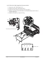


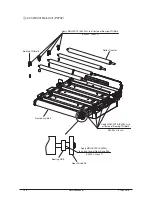


4.2.3.24 Remove the Stay-Guide-L-Assy
(1) Remove the scanner. (See Sub 4.2.1)
(2) Remove the left side cover. (See Sub 4.2.3.1)
(3) Remove the two screws (silver) to remove the Shield-Clamp.
(4) Remove the three screws (silver) to remove the Stay-Guide-L-Assy.
(5) Unthread the cables from the Guide Cable.
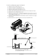
(6) Remove the Plate-Shield-Front(n). (See Sub 4.2.3.16)
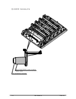
(7) Unplug the connectors to from the PUCU board.
(8) Disconnect the cable carefully not to deform the Shield-Clamp-Base.
<Instruction on reassembly>
To clamp the cable between the Shield-Clamp-Base and the Shield-Clamp, be sure to clamp the
part of the cable wrapped with a conductive tape.
Shield-Clamp-Base
PUCU-PCB
Y108500-4
Service Manual
91


