background image


1

8

1.5.2 Network Interface Specification

1.5.2.1  Outline of Network Interface

Table 1.5.2  Basic Specification of Network Interface

Protocol Family

Network Protocol

Application

TCP/IP

IPz4, TCP, ICMP, UDP

LPR, RAW

SNMPv1

DHCP/BOOTP

HTTP

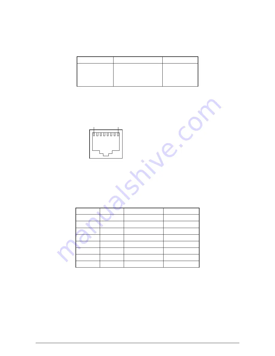
1.5.2.2  Network Interface Connector and Cable

(1)  Connector
 

100 BASE-TX/10 BASE-T (automatic switch, no simultaneous use)


Connector pin arrangement

(2)  Cable
 

Unshielded twist pair cable with RJ-45 connector (Category 5 is recommended.) 

1.5.2.3  Network Interface Signal

Pin No.

Singles

Single Direction

Functions

1

TXD+

FROM PRINTER

Send Data +

2

TXD-

FROM PRINTER

Send Data -

3

RXD+

TO PRINTER

Received Data +

4

-

-

Unassigned

5

-

-

Unassigned

6

RXD-

TO PRINTER

Received Data -

-

-

Unassigned

-

-

Unassigned

Y108500-4

Service Manual

15

Содержание d-Color MF1600

Страница 1: ...MULTIFUNCTIONAL COLOUR PRINTER d color MF1600 MF2000 SERVICE MANUAL code Y108500 4 ...

Страница 2: ...PUBLICATION ISSUED BY Olivetti S p A 77 Via Jervis 10015 Ivrea TO Italy Copyright 2007 Olivetti All rights reserved ...

Страница 3: ...ssible we make no warranty of any kind expressed or implied as to the accuracy of the information contained herein Oki Data assumes no responsibility to the damages caused or claimed to have been caused by the user as a result of repair adjustment and or change using this manual Parts of this product are delicate and can be damaged unless properly handled We strongly recommend the user to maintain...

Страница 4: ...n 31 3 2 MFP Unpacking Procedure 33 3 3 MFP Installation Instructions 34 3 4 Packed Units and Attachments 35 3 5 Assembly Procedure 36 3 5 1 MFP Main Body 36 3 5 2 Power Cable Connection 43 3 5 3 Installation of Optional Components 45 3 5 4 Confirm the Recognition of Option 49 3 6 Configuration Page Print 50 3 7 Network Information Print 52 3 8 Connection Procedures 53 3 9 Checking of User Paper 5...

Страница 5: ... 4 2 3 18 Plate shield rear 84 4 2 3 19 PRE board toner sensor board Gear idle dram 85 4 2 3 20 Main motor Solenoid 86 4 2 3 21 Belt motor High voltage board Cover open switch 88 4 2 3 22 Low voltage power supply Low voltage fan 89 4 2 3 23 M32 Board Main Board 90 4 2 3 24 Remove the Stay Guide L Assy 91 4 2 3 25 Disassembly of the Stay Guide L Assy 92 4 3 Lubricating points 93 5 Regular Maintenan...

Страница 6: ...6 5 2 9 Fuser Error Service call 170 177 188 6 5 2 10 Motor Fan Error Service call 127 189 6 5 2 11 Print Speed is Slow Low Performance 190 6 5 2 12 LED head is not recognized Error 131 132 133 134 190 6 5 2 13 Toner cartridge is not recognized Error 540 541 542 543 191 6 5 2 14 Fuse Cut Error Service call 150 155 192 6 5 2 15 Dew Condensation Errors Service call 123 192 6 5 2 16 RFID Related Erro...

Страница 7: ...B2 0 K LED HEAD Y LED HEAD M LED HEAD C LED HEAD K Tag Y Tag M Tag C Tag K Toner Sensor Y Toner Sensor Toner Sensor PCB ID Fuse Cut terminal LED FUSE LED FUSE LED FUSE LED FUSE K ID UP DOWN High Voltage Power Unit ENV Sensor Belt Unit BELT FUSE Cover Open SW BOURBON DCON ASIC Spilytas ASIC ARMORED Low Voltage Power Unit AC Front Sensor PCB Rear Sensor Relay PCB FAN AC SW AC Inlet Fuser Unit LOW TH...

Страница 8: ...AD C LED HEAD K Tag Y Tag M Tag C Tag K Toner Sensor Y Toner Sensor Toner Sensor PCB ID Fuse Cut terminal LED FUSE LED FUSE LED FUSE LED FUSE K ID UP DOWN High Voltage Power Unit ENV Sensor Belt Unit BELT FUSE Cover Open SW BOURBON DCON ASIC Spilytas ASIC ARMORED Low Voltage Power Unit AC Front Sensor PCB Rear Sensor Relay PCB FAN AC SW AC Inlet Fuser Unit LOW TH FRM TH UP TH SIDE TH Temperature S...

Страница 9: ...nters are composed of the following parts Scanner part Electronic photography process part Paper path Control part CU part PU part Operation panel Power supply parts high voltage part low voltage part Figure 1 2 shows the composition of the MFP Y108500 4 Service Manual 9 ...

Страница 10: ...1 3 Offer of Options This product can be installed with the following option 1 Additional memory board 256MB 10 Service Manual Y108500 4 ...

Страница 11: ...6MB ROM Program total capacity 8MB Power Consumption Power input 110 127VAC Range 99 140VAC 220 240VAC Range 198 264VAC Power saving mode Below 30W Idle 110W Normal operation 400W Peak 980W Operation Environment temperature In operation 10 32 17 27 temperature at full color printing with quality guaranteed At stand by 0 43 power off In storage 1 year max 10 43 with drum and toner At transport 1 mo...

Страница 12: ...ustom size government postcard reply paid postcard end opening envelope legal 13 13 5 14 letter ezecutive A4 A5 B5 A6 C5 DL Com 9 com 10 monarch custom size government postcard reply paid postcard end opening envelope banner up to 1200mm In case length is over 356 width would be up to 210 to 215 9 1st tray 100mm x 14 mm Min paper size Manual feeder 100mm x 14 mm 1st tray 64 120gsm Manual feeder 64...

Страница 13: ...able 3 Type face N A Luster riser N A Bar code N A OCR N A Japanese PCL font N A Font Japanese PS font N A Option Removable RAM set 256MB USB IF logo Available Windows logo Available Others Operation by UPS Operation by UPS outage free power supply is not guaranteed Do not use UPS Y108500 4 Service Manual 13 ...

Страница 14: ...or Printer side B receptacle Upstream port Equivalent of UBR24 4K5C00 made by ACON Connector pin arrangement Cable side B plug off 2 Cable Cable length Specification Cable of USB2 0 spec of less than 5m less than 2m is recommended Shielded cable is used here 1 5 1 3 UBS Interface Signal Name of Single Function 1 Vbus Power Supply 5V red 2 D Data transmission white 3 D Data transmission green 4 GND...

Страница 15: ...or and Cable 1 Connector 100 BASE TX 10 BASE T automatic switch no simultaneous use Connector pin arrangement 2 Cable Unshielded twist pair cable with RJ 45 connector Category 5 is recommended 1 5 2 3 Network Interface Signal Pin No Singles Single Direction Functions 1 TXD FROM PRINTER Send Data 2 TXD FROM PRINTER Send Data 3 RXD TO PRINTER Received Data 4 Unassigned 5 Unassigned 6 RXD TO PRINTER ...

Страница 16: ...pment Electrified toner is adhered to the static latent image on the OPC drum by static electricity and a visible image is formed on the OPC drum surface 4 Transcript A sheet of paper is put upon the OPC drum surface and the toner image is transferred on the paper by impressing electric charge on its back side by the transcript roller 5 Drum Cleaning Drum cleaning blade eliminates the remaining to...

Страница 17: ...rge on the radiated portion of the OPC drum surface abates by intensity of the light and a static latent image is formed on the OPC drum surface 4 Development Adhere the toner to the static latent image on the drum surface and change it to the toner image 1 The sponge roller let the toner adhere to the development roller 2 The static latent image on the OPC drum surface is changed to a visible ima...

Страница 18: ...ctric charge from the back side by the transcript roller When a high voltage is impressed on the transcript roller the electric charge generated by the transcript roller moves over to the paper surface at the interfacing part of the transcript roller and the toner is absorbed to the paper surface from the OPC drum surface 18 Service Manual Y108500 4 ...

Страница 19: ... Temperature Setting Middle temp High temp Middle temp Low temp Setting of Fusing Temperature 6 Fusing The toner image transferred on the paper is impressed with heat and pressure and is fused to the paper when the paper passes through the heat roller and the back up roller Further a thermostat is equipped for the safety s sake and if the temperature of the heat roller rises above a certain degree...

Страница 20: ... transferred and remaining on the OPC drum is scraped away by the drum cleaning blade and is collected in the waste toner area of the toner cartridge 8 Belt Cleaning The toner remaining on the transcript belt is scraped away by the belt cleaning blade and is collected in the waste toner box of the transcript belt unit 20 Service Manual Y108500 4 ...

Страница 21: ...per is feeded by the manual feeder it is transported by the resist roller U Then the paper transported is developed into a toner image not yet fused on the paper through electronic photography process in the order of KYMC After that the image is fused by heat and pressure while passing through the fusing unit After fusing the paper is discharged on the face up or face down stacker through the disc...

Страница 22: ... 2 1 while the solenoid is on and the resist motor turns counterclockwise a sheet of paper is transported until the IN1 sensor is on When the solenoid is on the paper feeding roller operates 2 When the paper turns the IN1 sensor on a certain more sheets of paper are transported and thrusted against the resist roller This process corrects the paper skew 3 As shown in Figure 2 2 turn the solenoid of...

Страница 23: ...lt starts to operate The belt unit is composed of drums of each color above and the transport rollers immediately below them with the transport belt in between When a certain voltage is impressed the transport belt and the transport rollers send the paper on the transport belt to the fuser while transferring the toner images on the drums of each color Y108500 4 Service Manual 23 ...

Страница 24: ... 1 The up and down movements of the ID units are performed by the drive of the lift up motor 2 Figure 2 5 shows movements of each ID unit at the time of printing When the lift up motor turns clockwise the lift up link slides to the left and each ID unit is in the state of down as shown in Figure 2 6 That condition enables color printing 3 Figure 2 6 shows movements of each ID unit at the time of m...

Страница 25: ...is roller fuses the toner image on the paper with heat and pressure 2 At the same time the output roller turns and sends out the paper 6 Cover Open Operation of Color Registration Sensor and Density Sensor 1 As shown in Figure 2 8 when the fuser motor turns clockwise the cover open gear also turns and the covers of the color registration sensor and the density sensor will open 2 When the fuser mot...

Страница 26: ...ration At the time of switching the power on At the time of closing the cover after opening it over 5 seconds When over 400 sheets are printed after a color registration was made previously Correction errors can be caused by the amount of toner which generates the pattern toner stain on the sensor malfunction of shutter opening and closing However as an error may not be displayed on the operation ...

Страница 27: ... is found replace the shutter unit BELT REFLXERRR Confirmation 4 When the above is displayed confirm the cleaning state of the toner remaining on the belt surface besides the above confirmations 1 2 and 3 Remove the belt unit and confirm if the belt surface is cleaned neatly by turning the drive gear placed in the left rear side Replace the belt unit if the toner remains on the belt surface and th...

Страница 28: ...t one of the 4 ID count values is almost new at the time when the power is to be switched on When the ID count value is over 500 after the previous work performance Correction error can be caused by the amount of toner which generates the pattern toner stain on the sensor malfunction of shutter opening and closing However as an error may not be displayed on the operation panel it may be necessary ...

Страница 29: ...neatly DENS SHUTTER ERR Confirmation 3 Confirm adequacy of the opening and shutting of the sensor shutter by MOTOR CLUTCH TEST of the maintenance utility If a malfunction is found replace the shutter unit DENS ID ERR Confirmation 4 Remove the ID unit to confirm if the surface of the drum is covered with abnormal amount of toner Then replace the LED head if the focus blurs or replace the ID unit Wh...

Страница 30: ...r Toner Counter Principle After the image data is developed into 2 value data to enable printing using the MFP the print dot number is counted by the LSI The amount of the toner used is counted from the above count value and the remaining amount is displayed On the other hand detection of the low toner by the toner sensor is physically made when the amount of the toner remaining in the cartridge c...

Страница 31: ...directed by the Manual A fire may break out Do not insert a thing in the vent hole Electric shock fire or injury may occur Do not place a cup with water on the MFP Electric shock or fire may occur Do not touch the fuser unit when you open the printer cover Burn may occur Do not throw the toner cartridge or image drum cartridge into fire Burn may occur by the dust explosion Do not use a highly flam...

Страница 32: ... monitor TV When the MFP is to be moved hold both ends of the printer This MFP weighs about 28kg and should be lifted by 2 or more persons When to switch the power on or while printing do not come near the paper exit of the MFP Injury may occur As regards the items of caution explain to the customer showing the items of caution of the User s Manual Particularly explain fully about the power supply...

Страница 33: ...ure Personal injuries may occur This MFP weighs about 28kg So lift it up with 2 or more persons Open the upper lid Take out the accessory box Remove the upper buffer material Take out the equipment Y108500 4 Service Manual 33 ...

Страница 34: ...0 relative humidity Maximum Wet Bulb Temperature 25 C Be careful not to be bedewed When the MFP is to be installed at a place where the humidity is less than 30 use a humidifier or a static electricity prevention mat Installation Space Place the MFP on a flat desk with enough space for the legs of the MFP Secure enough space around the MFP Top View Side View 34 Service Manual Y108500 4 ...

Страница 35: ... body d Color MF1600 2000 Image Drum Cartridges with Starter Toner Cartridges 4 sets installed in the MFP Explain to customers that the toner cartridge and the image drum cartridge are separable MFP Software CD ROM Power Cord Warranty and Registration Card Users Manual Setup Guide Users Manual on CD ROM Note The printer cable is not included in the accessories Personal injuries may occur This MFP ...

Страница 36: ...f MFP and open the document cover Then remove the 3 adhesive tapes and protection pad 2 Pull out the paper cassette 3 Lift the scanner 4 Press the open button and open the top cover 5 Remove the stopper release orange color while pushing down the lever blue of the fuser unit in the direction of the arrow Note Explain to the customer that the stopper release must be kept as it would be used at the ...

Страница 37: ...eave it more than 5 minutes under the room light Do not move the blue lever of the cartridge at this stage Starter Toner Cartridge Image Drum Cartridge 2 Place the image drum cartridge on a flat desk remove the tape which fastens the protection sheet and pull it out in the direction of the arrow Note Do not work on the image drum off the desk top 3 Pull out protection sheet 2 from the image drum c...

Страница 38: ...f the arrow Note The starter toner the toner cartridge attached to the product at the time of purchase can print approximately 1 000 sheets of A4 paper in case of 5 coverage Approximately 500 sheets in case of OEL AOS specification Confirm whether the lever of the toner cartridge is turned fully in the direction of the arrow when Toner Empty Messages are displayed in the LCD Blue Lever 38 Service ...

Страница 39: ...e ADF Doc Lid Note If you need to move your MFP or Scanner unit for repair or any other reason be sure to lock your Scanner before moving To lock your Scanner please do the following 1 Turn off your MFP 2 If the scanning head is not located at the left end turn the MFP on to return the scanning head to the left end After the scanning head is returned to the left end turn the power supply off 3 Mov...

Страница 40: ...he sheets of paper and arrange up down left and right properly 4 Make the printable side down and set the paper Note Place the paper in front of the paper cartridge Set the paper not to exceed mark of the paper guide 250 sheets weighing 70kg 5 Fix the paper by the paper stopper 6 Return the paper cassette to the MFP Printing face down Paper Stopper Paper life display 40 Service Manual Y108500 4 ...

Страница 41: ...ard Manual Feed Opening 2 Conform the manual feeding guide to the size of the paper 3 Arrange the left and right of the paper Manual Feeding Guide Manual feeding opening Manual Feeding Guide 4 Make the printing side up and insert the paper straight to the rear end along the manual feed guide Y108500 4 Service Manual 41 ...

Страница 42: ...ee of staples paper clips and is not tore out 2 If you have multiple pages fan your document s to avoid occasional paper jam The ADF holds up to 50 pages at one time 3 Place your document s with the text FACE UP in the ADF 4 Adjust the Paper Guides to center the document s in the ADF On the Document Glass 1 Place your original with the text face down on the document glass 42 Service Manual Y108500...

Страница 43: ...c cord at the place liable to be stepped on and do not put things on the electric cord Do not bundle up or tie up the electric cord Do not use the damaged electric cord Do not put many loads on one electric outlet Do not connect this MFP to the same outlet with other electric machines Particularly erroneous operation may occur by electric noise when the same outlet is shared by the air conditioner...

Страница 44: ... placed in the OFF O position Earth Terminal Earth Cable 2 1 1 Insert the electric cord in the MFP 2 Insert the plug in the outlet after connecting the earth cable with the earth cable terminal of the outlet Press ON I of Power Switch 44 Service Manual Y108500 4 ...

Страница 45: ...B memory before use Switch the power supply of the MFP off and pull out the electric cord Note If installed with the switch on an electric shock or a trouble to the MFP may occur O I Lift the scanner and open the top cover Top cover Open Button Screw Eliminate static electricity by touching a screw Type On board Memory slot Total N A Standard 64MB 64MB 128MB MEM256D 64MB 256MB 320MB C3530MFP C3520...

Страница 46: ...te liable to injury take care fully at the time of handling Do not expose the image drum cartridge to the direct sunshine or bright light approximately more than 1 500 lux Do not leave it more than 5 minutes under the room light Remove the belt unit 1 Turn the lock levers blue 2 in the direction of and release the lock 2 Hold the lever blue of the belt unit and take out the belt unit gently 46 Ser...

Страница 47: ...onnector terminal 1 Neutralize static electricity by letting the bag touch the metal part before taking out the memory from the bag 2 Pay attention to the direction of the memory There is a cut on the terminal part of the memory to fit it into the connector of the slot 3 Insert the memory in the empty slot and bring it down to the circuit board side Memory Cover Knob Y108500 4 Service Manual 47 ...

Страница 48: ...se the memory cover 1 Close the memory cover Confirm that it is firmly locked Install the belt unit 1 Hold the belt unit lever blue and install the belt unit 2 Turn the lock lever blue 2 in the direction of and confirm that the belt unit is firmly fixed 48 Service Manual Y108500 4 ...

Страница 49: ...h on 3 5 4 Confirm the Recognition of Option In order to confirm that the items of option are correctly installed conduct the menu map printing referring to 3 6 Configuration Page Print 1 Confirm Recognition of Additional Memory Confirm the contents of the configuration pages Confirm the total memory size displayed as TOTAL MEMORY SIZE in the header portion Y108500 4 Service Manual 49 ...

Страница 50: ...paper in the tray 2 From the panel menu select Menu Press the down button to go to Menu and then press the enter button 3 Select Print Information Press the down button to go to Print Information and then press the enter button 4 Select Configuration 5 Select Execute Sample In case of d Color MF2000 50 Service Manual Y108500 4 ...

Страница 51: ... Sample In case of d Color MF1600 Y108500 4 Service Manual 51 ...

Страница 52: ...m the network information print 1 Push the TEST switch beside the network connector on the back of the MFP for 5 seconds and release Then the network information will be printed Sample In case of d Color MF1600 52 Service Manual Y108500 4 ...

Страница 53: ...switch off the power of the MFP at this step in order to ensure installation of the MFP driver and USB driver later Connect the MFP with the computer 1 Plug the USB cable into the USB interface connector of the MFP 2 Plug the USB cable into the USB interface connector of the computer Note Be careful not to insert the USB cable into the network interface connector Or else it may cause troubles Prep...

Страница 54: ... cable on a core 2 times and then close the core case to fix it The core must be about 50 60mm away from the connector Network Interface Connector Switch off the power of the MFP and computer Connect the computer and MFP 1 Plug the Ethernet cable into the network interface connector of the MFP 2 Plug the Ethernet cable into the hub 54 Service Manual Y108500 4 ...

Страница 55: ...each core 1 time and then close the core cases to fix them The cores must be about 80 100mm away from the each connector Cable Core Name Part No Core shape Winding count C3520MFP C3530MFP for USB SFT 59SN 1051007C0001 Long Type 0 for LAN TFT 152613N 1051009C0002 Short Type 2 for TEL SFT 59SN 1051007C0001 Long Type 1 X for LINE SFT 59SN 1051007C0001 Long Type 1 X Use for Fax Only d Color MF2000 for...

Страница 56: ... of the printer menu setting 3 Thickness of paper for both side printing is 65 90kg in weight 75 105g m2 4 Set up of media weight and media type is not necessary for postcards and envelopes Memo When Heavy and Ultra Heavy of Media Weight and Label Paper of Media Type are set up the printing speed becomes slow Types Weight Setting values of the printer menu setting Setting 2 for Media weight of the...

Страница 57: ...ocedures for parts assemblies and component units While those replacement procedures refer to the disassembling of parts follow the same procedures inversely for reassembling them The part numbers 1 2 etc employed in this manual are different from those assigned in the corresponding configuration diagrams of Disassembly for Maintenance 43605601TL and RSPL 43605601TR 4 1 Precautions on the replacem...

Страница 58: ...nter 2 Remove the four screws silver hold the front side of the stay on each side of the printer so as not to allow the scanner to tilt back 3 Put the scanner back in its original horizontal position 4 By holding the scanner by the right and left stays and vertically lifting it up separate the scanner from the printer Note When attaching the scanner to the printer bring down the scanner onto the p...

Страница 59: ...ray 1 Gently open the ADF top cover 2 Turn the lever in the direction of the arrow to put the frame assembly and the paper tray upright 3 Remove the two screws black and then the paper tray Lever ADF top cover Frame Assy Y108500 4 Service Manual 59 ...

Страница 60: ...this operation the inner hooks of pad is removed in direction of the arrow A Note In order to cause damage to the surface of roller please take attention to use the tool when this operation 3 Push another side of pad forward in direction of the arrow B with the tool inserted 4 Exchange to the new pad in the direction of the arrow A B B Driver 60 Service Manual Y108500 4 ...

Страница 61: ...paper tray upright 5 Remove the two screws black 6 Restore the frame Assembly and the paper tray in their original positions 7 Release the frame Assembly from the hook near its supporting point on each side of the scanner to remove the Assembly and the paper tray 8 Remove the three screws black to remove the ground plate and 9 Unplug all the connectors and remove the ADF PCBA ADF top Cover Lever Y...

Страница 62: ...Note Be careful not to remove or insert the FFC cable at an angle from the connector on the back of the operation panel Assembly their terminals are damaged Removing operation panel PCBA 1 Pull the FFC cable out of the LCD straight in the direction of the arrow 2 Remove the six screws black 3 Remove the operation panel PCBA Note Removing or inserting the FFC cable at an angle from the connector on...

Страница 63: ...ys are pulled up there is reaction 3 Remove the six screws black and then the MPCBA cover 4 Turning the shield USB in the direction of the arrow remove it 5 Remove the four screws black and then the top shield Assembly 6 Disconnect all the connectors to remove the MPCBA board Stay_L Y108500 4 Service Manual 63 ...

Страница 64: ... Unlike the other screws used in the printer the screws are long 2 Reverse the scanner and put the stays L and R upright 3 Remove the six screws black and then the MPCBA cover 4 Unfix the ground wire by removing the screw black 5 Remove the ADF connector Long type Lower ADF connector 64 Service Manual Y108500 4 ...

Страница 65: ...in and open the document cover the ADF assembly 5 8 Slightly lift the ADF assembly As illustrated unlock each hinge of the ADF assembly by inserting closed curved tip tweezers and in the direction of the arrow lightly pressing the tweezers Lift and remove the ADF assembly Note For the structure of each hinge joint of the ADF assembly see the cross section view shown below Y108500 4 Service Manual ...

Страница 66: ...ove the stopper Assembly 3 Remove the two long screws black for metal use black the four small resin use screws black and then the stay left inner cover 4 Remove the two screws black with washer to take out the USB board 5 Remove the connector from the USB board for metal with washer connector long type 66 Service Manual Y108500 4 ...

Страница 67: ...top cover 3 Unhook the hooks of the Stay arm L Stay arm R and Link Head 4 Open the front cover 5 Remove two screws silver four claws A and a claw B to remove the left side cover Tool No 1 Top cover Link Head Stay arm R Stay arm L Front cover ClawA ClawB Y108500 4 Service Manual 67 ...

Страница 68: ...er 3 Unhook the hooks of the Stay arm L Stay arm R and Link Head 4 Open the front cover 5 Remove two screws silver four claws A and a claw B to remove the right side cover Tool No 1 Top cover ClawB ClawA Front cover Link Head Stay arm R Stay arm L 68 Service Manual Y108500 4 ...

Страница 69: ...2 3 Remove two screws silver Tool No 1 4 As shown in the drawing put the flat blade screwdriver Tool No 3 into a hole A to remove two claws A 5 Detach two claws B by hand and then remove the rear cover assembly 6 Lift the rear cover bottom upward to remove it ClawA ClawA ClawB HoleA HoleA HoleA HoleA Hole Y108500 4 Service Manual 69 ...

Страница 70: ...4 2 3 4 Front cover 1 Remove the Shaft Cover and the stay and then remove the Shaft Cover and the Front Cover 70 Service Manual Y108500 4 ...

Страница 71: ...2 3 3 6 Remove the plate heat See Subsection 4 2 3 18 7 Remove the plate shield front See Subsection 4 2 3 16 8 Remove a screw silver 9 Remove the M32 PCB main board See Subsection 4 2 3 23 and then remove the head cable FFC and the RFID cable 10 Remove two E type retaining rings two sprint torsions and the top cover assembly ViewA ViewA RFID K Y M C Head cable FFC BLA PCB Main circuit board PCB Y...

Страница 72: ...4 2 3 6 Top cover 1 Remove the top cover assembly See Subsection 4 2 3 5 2 Remove nine screws black to remove the top cover 9 72 Service Manual Y108500 4 ...

Страница 73: ... direction of the arrow B Portion A 4 After removing the head cable FFC apply force in the direction of the arrow X as shown in Figure 2 Detach a hook C first and then a hook D to remove the LED assembly 5 Remove the LED assembly SU spring Top cover Hook C Figure 1 X Hook D Figure 2 Portion A B Y108500 4 Service Manual 73 ...

Страница 74: ...2 3 6 2 Remove the top cover See Subsection 4 2 3 7 3 Remove two screws silver and all connectors to detach the LUM board RFID reader writer 4 Detach six claws A and two claws B engaging with the plate inner to remove RFID assembly Claw A Claw B 74 Service Manual Y108500 4 ...

Страница 75: ... assembly 1 Lift the scanner 2 Open the top cover 3 Open the front cover 4 Remove the four screws silver and then detach the OP frame assembly while pushing the side cover outward Tool No 1 Y108500 4 Service Manual 75 ...

Страница 76: ... 4 2 3 9 2 Detach a claw A to remove the frame OP 3 Detach a claw B and the button lock to remove the lever lock 4 Remove a spring 5 Detach four claws C and the cover assembly OP 6 Remove a spring Claw A Claw A Claw B Claw B Claw C Claw C 76 Service Manual Y108500 4 ...

Страница 77: ...2 3 4 5 Remove the Lever_Lock_Assembly 6 Remove the plate shield front See Subsection 4 2 3 16 7 Detach a connector connecting to the feeder unit from the BLA board main board 8 Remove four screws silver to remove the feeder unit 9 Detach claws to remove the cover sensor 10 Remove the MIP board front sensor board 4 HOP BLA PCB Main circuit board PCB BLA PCB Main circuit board PCB Y108500 4 Service...

Страница 78: ...4 2 3 12 Manual feeder unit 1 Open the manual feeder 2 Hold both ends of the manual feeder and pull it in the direction of the arrow to remove it about 45 78 Service Manual Y108500 4 ...

Страница 79: ...eft side cover See Subsection 4 2 3 1 3 Remove the right side cover See Subsection 4 2 3 2 4 Remove the rear cover See Subsection 4 2 3 3 5 Detach the supporting points of the face up tray with a flat blade screwdriver Tool No 3 Support point 2 places Y108500 4 Service Manual 79 ...

Страница 80: ...ght side cover See Subsection 4 2 3 2 4 Remove the rear cover See Subsection 4 2 3 3 5 Remove the top cover assembly See Subsection 4 2 3 5 6 Remove the color registration assembly See Subsection 4 2 3 17 7 Detach two latches at the lower part of the guide eject assembly to remove the guide eject assembly Latche 80 Service Manual Y108500 4 ...

Страница 81: ...vide the minto the guide eject lower and the guide eject upper 3 Detach a claw B Remove three gear idle ejects the shaft assembly eject FD and the shaft assembly eject FU 4 Remove the eject sensor and the lever eject sensor from the guide eject lower View A View A claws B Claws A Y108500 4 Service Manual 81 ...

Страница 82: ...4 2 3 16 Plate shield front 1 Remove two screws silver and remove the plate shield front claws 82 Service Manual Y108500 4 ...

Страница 83: ...o screws silver to remove the plate heat 4 Remove two screws silver to detach two connectors and one FFC Then remove the color registration assembly 5 Detach two supporting points to remove the frame shutter 6 Remove two screws silver to remove the color registration sensor board 7 Remove a screw silver to remove the density sensor board Fulcrums Y108500 4 Service Manual 83 ...

Страница 84: ...Subsection 4 2 3 5 6 Remove the color registration assembly See Subsection 4 2 3 17 7 Remove the plate shield front See Subsection 4 2 3 16 8 Remove the low voltage power supply See Subsection 4 2 3 22 9 Remove the BLA board main board See Subsection 4 2 3 23 10 Remove two screws silver to remove the plate heat 11 Detach latches of the gear lift up to remove a shaft 12 Remove three screws silver t...

Страница 85: ...n 4 2 3 2 3 Remove seven screws silver and remove bracket outer 4 Remove the drum idle gears and 5 Remove the idle gear 6 Remove ID lift up gears and 7 Remove the cove plate by sliding back the latch A 8 Detach the latch B to remove the Board PRE and the spring contact 7 8 LatchB LatchA Toner sensor cable Front Y108500 4 Service Manual 85 ...

Страница 86: ...mbly See Subsection 4 2 3 17 12 Remove the plate shield rear See Subsection 4 2 3 18 13 Take out two screws silver to remove the part A and the side plate R assembly 14 Remove a screw silver to remove the plate lockout ID 15 Remove five screws silver to remove the part B and the bracket inner 16 Remove two screws silver to remove the Fuser motor 17 Remove two screws silver to remove the DC motor 1...

Страница 87: ...A A B clawC clawE clawD Y108500 4 Service Manual 87 ...

Страница 88: ...onnector and claw A to remove the cover open switch 4 Remove a screw silver and a screw black and then detach seven claws B to remove the high voltage board 5 Remove a screw silver to remove belt motor CN4 TR K TR M TR Y TR C High voltage power supply Cover open switch Claws A Claw A Claw A Claws B Cover opening switch cable route chart 88 Service Manual Y108500 4 ...

Страница 89: ...ut the low voltage power supply to the position at which the AC switch connector and the fuser interface connector can be removed 8 Detach the AC switch connector and the fuser interface connector and remove the low voltage power supply 9 Pull out a connector of the FAN in the direction of the arrow to extract the FAN CN5 CN5 1 CN101 CN102 CN2 PRN PCB POWER connector Short circuit plug for CN5 Cla...

Страница 90: ... 16 5 Detach all connectors connecting to the M32 board main board 6 Remove the rear cover See Subsection 4 2 3 3 7 Remove the low voltage power supply See Subsection 4 2 3 22 8 Remove seven five screws silver and two screws silver to remove the M32 board main board View A View A 7 Only C3530 HEAT IDUP HOP HSDL FSNS DCID SSNS OP732 OP724 BELT HVDLT RSNS CN1 POW Note Numbers of screws C3530 7 C3520...

Страница 91: ... Assy 5 Unthread the cables from the Guide Cable 6 Remove the Plate Shield Front n See Sub 4 2 3 16 7 Unplug the connectors to from the PUCU board 8 Disconnect the cable carefully not to deform the Shield Clamp Base Instruction on reassembly To clamp the cable between the Shield Clamp Base and the Shield Clamp be sure to clamp the part of the cable wrapped with a conductive tape Shield Clamp Base ...

Страница 92: ...ssy 4 Unthread the cable from the Guide Cable 5 Remove the two screws silver and the screw silver to remove the Shield Cable Outer 6 Remove the two screws silver to remove the Shield Drawer L 7 Disconnect the two connecting cable from the back of the drawer connecor ViewA ViewA Hook Cable CONN Cord Wire Power blue line chamfering CONN Cord Wire Signal View A 92 Service Manual Y108500 4 ...

Страница 93: ... in the midst of a disassembling job However if lubricating oil has been wiped off supply the specified oil Lubricating work 1 Symbols and names of oils EM 30L MOLYKOTE EM 30L HP 300 MOLYKOTE HP 300 PM Pan Motor Oil 10W 40 or ZOA 10W 30 2 Boundary samples of grease Class Amount of grease cc W mm Sample S A B C D E F 0 0005 0 003 0 005 0 01 0 03 0 05 0 1 1 24 2 25 2 67 3 37 4 86 5 76 W 7 26 Y108500...

Страница 94: ... Class A Gear Planet HP Stopper HP Gear Z24 50 HP The side of groove EM 30L Class C Gear tooth surface and end surface EM 30L Class C Shaft Hopping Gear bottom surface EM 30L Class C Ratch portion Hatching portion EM 30L Class C Guide Cassette R Apply MOLYKOTE EM 30L to the hatched areas EM 30L Class C Guide Cassette L Apply MOLYKOTE EM 30L to the hatched areas EM 30L Class C 94 Service Manual Y10...

Страница 95: ...e hatched areas portions shown in the figure below before assembly At both sides Fulcrum of rotation and side The application of grease protruding over on the paper carriage surface is not permitted Class C Holder Gear A Apply MOLYKOTE EM 30L to the hatched areas EM 30L Class C Y108500 4 Service Manual 95 ...

Страница 96: ...ass C Grease is not applied to a metal shaft Gear Idle Drum Z24 117 Gear Idle Drum Z55 Apply MOLYKOTE EM 30L to the gear tooth surface EM 30L Class F Apply MOLYKOTE EM 30L to the gear tooth surface EM 30L Class F Apply MOLYKOTE EM 30L to the end face EM 30L Class C Apply MOLYKOTE EM 30L to the end face EM 30L Class C Gear Idle Drum Z55 Gear Idle Drum Z24 117 96 Service Manual Y108500 4 ...

Страница 97: ...ched areas EM 30L Class A Link Liftup L Apply MOLYKOTE EM 30L to the hatched areas EM 30L Class A Apply MOLYKOTE EM 30L to the gear tooth surface EM 30L Class A Apply MOLYKOTE EM 30L to the hatched areas EM 30L Class A Class S OR board PRE After palish the terminals to luster with BEMCOT M 3 Tetfa C 9300 is soaked cotton swab a little Class S and it coated on terminals 32 places 3 43194601 Cover A...

Страница 98: ...ssy Regist L 43210301 Holder Assy Regist R Holder Regist L Apply MOLYKOTE EM 30L to the hatched areas EM 30L Class C Holder Regist R Apply MOLYKOTE EM 30L to the hatched areas EM 30L Class C 98 Service Manual Y108500 4 ...

Страница 99: ...to the hatched areas HP 300 Class C Cam Release Lever Release Not allowed to stain the area with grease Apply MOLYKOTE EM 30L to the sliding portions hatching portions EM 30L Class S The application of grease protruding over on the paper carriage surface is not permitted Y108500 4 Service Manual 99 ...

Страница 100: ...urface EM 30L Class C Gear Idle Exit Z19 Gear Idle Exit Z19 Gear Idle Exit Z21 Bearing Eject FD FU 2 points Apply MOLYKOTE EM 30L to the hatched areas EM 30L Class C Apply MOLYKOTE EM 30L to the hatched areas In gear bearing part EM 30L Class C 100 Service Manual Y108500 4 ...

Страница 101: ... 30L Class C Apply MOLYKOTE EM 30L to the hatched areas EM 30L Class C Apply MOLYKOTE EM 30L to the hatched areas EM 30L Class C Apply MOLYKOTE EM 30L to the end face EM 30L Class C Apply areas to grease 4 points Plate Shield Rear Caulking Gear Idle Belt Y108500 4 Service Manual 101 ...

Страница 102: ...n L Spring Torsion R Apply PM with a brush to the portion of the slot of solid coiling of this torsion spring 2 places Both Sides PM Class C Apply MOLYKOTE EM 30L to the hatched areas EM 30L Class C Plate Assy Side R 102 Service Manual Y108500 4 ...

Страница 103: ...ply MOLYKOTE EM 30L to the hatched area EM 30L Class C Guide R Guide L Apply MOLYKOTE EM 30L to the hatched area EM 30L Class C Bracket CL Assy Not applying grease to a part of a metal plate Bracket CL L Y108500 4 Service Manual 103 ...

Страница 104: ... Bearing TR Belt Roller Transfer Frame Assy Belt Bearing GSB Gear Drive Z36 Apply MOLYKOTE EM 30L to all inside of Bearing TR Belt EM 30L Class A Apply MOLYKOTE EM 30L to all inside of Bearing TR Belt EM 30L Class A 2 43216001 Belt Unit PX732 104 Service Manual Y108500 4 ...

Страница 105: ... Tetfa C 9300 is soaked cotton swab a little Class S and it coated on terminals 32 places 4361110x Board Assy PUCU 43420301 Stay Guide L Assy 43422201 Stay Guide R Assy 23mm EM 30L ClassB Flange contact area 23mm EM 30L ClassB Flange contact area Y108500 4 Service Manual 105 ...

Страница 106: ...43420101 Cover Assy Top Grease prohibition to this portion Apply MOLYKOTE EM 30L to the hatched area EM 30L Class A 106 Service Manual Y108500 4 ...

Страница 107: ...tay Arm L Apply Molykote to the valley part of flange EM 30L Class A Apply Molykote to the valley part of flange EM 30L Class A Apply Molykote to the all post surroundings EM 30L Class B Apply Molykote to the all post surroundings EM 30L Class B Y108500 4 Service Manual 107 ...

Страница 108: ...e clean your LED lens array Note Make sure to use soft tissues to clean the LED lens array 5 Regular Maintenance 5 1 Recommended substitutes It is recommended by our company that only heavy users should change the following parts If not changed the printing quality cannot be guaranteed and failures may arise White lines white stripes white defection light printing Note 1 Consumables image drum ton...

Страница 109: ... is extremely hot Do not touch it Personal injuries may occur OPEN button 2 Lift the scanner 3 Press OPEN button and open the top cover LED head 4 Lightly wipe the lens 4 points of the LED head with soft tissues Note Do not use solvents as methyl alcohol or thinner as they might cause damage to the LED head 5 Close the top cover 6 Lower the scanner Y108500 4 Service Manual 109 ...

Страница 110: ... feeding roller and pad If 391 paper jam happens frequently please clean your paper feeding roller and pad 1 Draw out the paper cassette 2 Get the cloths wet and wring it out Then use the cloths to wipe paper feeding roller large and paper feeding roller small Feed roller large Feed roller small Pad 3 Get the cloths wet and wring it out Then use the cloths to wipe the pad part of paper cassette 11...

Страница 111: ... cover The fuser unit is extremely hot Do not touch it Personal injuries may occur 4 Take out the image drum cartridge 1 Take out the 4 image drum cartridges and put them on a flat surface 2 Cover the 4 image drum cartridges with black paper Note The image drum the green cylinder is very easy to be damaged please be careful when handling it Don t put the image drum cartridges in direct sunlight or...

Страница 112: ...Take out the fuser unit 1 Pull the 2 blue lock levers of the fuser unit in the direction of the arrows 2 Hold the handle of the fuser unit and take it out 6 Use soft cloths or tissue paper to wipe the metal shaft 7 Set the fuser unit For more detailed information please refer to the Users Manual Setup part Change the fuser unit 8 Gently put the 4 image drum cartridges back into your MFP 9 Close th...

Страница 113: ...p cover 3 Pinch the ADF lock lever and turn the Kernel Assy up until it is locked 4 Using a soft cloth remove dirt with a sweeping action to the direction of the arrow Caution Do not use benzin thinner and alcohol 5 Get back the Kernel Assy to the initial position 6 Close the ADF Top Cover ADF Top Cover Y108500 4 Service Manual 113 ...

Страница 114: ...ith a soft cloth Caution Do not use benzin thinner and alcohol 3 Close the ADF Doc Lid 5 8 Cleaning the Flatbed glass When dirt is found on an image read by the Flatbed glass 1 Open the ADF Doc Lid 2 Wipe the Flatbed glass to remove dirt with a soft cloth Caution Do not use benzin thinner and alcohol 3 Close the ADF Doc Lid A 114 Service Manual Y108500 4 ...

Страница 115: ...Precautions when taking action on abnormal images 1 Do not bring your hand or any object in contact with the surface of the OPC drum 2 Do not expose the OPC drum to direct sun 3 Do not touch the fuser unit which can be very hot 4 Do not expose the image drums to light for over five minutes at the room temperature 6 4 Preparations for troubleshooting 1 Display of LCD The breakdown situation of this...

Страница 116: ...hecked capacity against the total capacity 1 2 3 4 5 RAM Check nnn 5 Initializing The PU firmware is starting up in Loader mode This error may occur in a user environment In that case the printer requires servicing by an engineer equivalent to S C 1 2 3 4 5 PU Flash Error 6 Initializing Communications with PU firmware has failed This error may occur in a user environment In that case the printer n...

Страница 117: ...ode The backlight stays on during shutdown 1 2 3 4 5 Power Save 10094 13 Normal Access Control function has been enabled 1 2 3 4 5 Access Control Enabled 10843 14 Normal Access Control function has been disabled 1 2 3 4 5 Access Control Disabled 10844 15 Normal Document is being discharged 1 2 3 4 5 Wait a Moment Removing Document 10848 16 Warning The life of the image drum is nearing its end The ...

Страница 118: ... warning COLOR Yellow Magenta Cyan Black 1 2 3 4 5 Incompatible Toner COLOR Press Start Button 10939 Y 10940 M 10941 C 10938 K 22 Warning The RFID chip of the toner cartridge is not compatible not a genuine product COLOR Yellow Magenta Cyan Black 1 2 3 4 5 Non Genuine COLOR Toner Press Start Button 10950 K 10951 Y 10952 M 10953 C 23 Warning The Region ID distribution channel of the toner cartridge...

Страница 119: ...ing 1 2 3 4 5 Belt Unit Near Life Press Start Button 10978 28 Warning The life of the fuser is nearing its end 1 2 3 4 5 Fuser Unit Near Life Press Start Button 10979 29 Warning Automatic density correction is in progress 1 2 3 4 5 Adjusting Density 10994 10988 30 Warning The displayed paper tray is empty This is treated as a warning until the empty tray is selected for printing TRAY Tray1 1 2 3 4...

Страница 120: ...inter initializing process 1 2 3 4 5 Shutting down 37 Error The printer has completed the shutdown process The LCD backlight goes out 1 2 3 4 5 Turn off power Shutdown OK 38 Error The entered PIN ID is invalid 1 2 3 4 5 Incorrect ID 39 Error The entered password is invalid This appears when moving to Admin Boot Menu 1 2 3 4 5 Incorrect Password 40 Error The toner is running low When Low Toner Stop...

Страница 121: ...after change in network settings 1 2 3 4 5 Wait a Moment Network Initializing 30956 44 Error Scanner unit configuration PnP process is in progress 1 2 3 4 5 Wait a Moment Checking Scanner 30958 45 Error A cover is open COVER Top Cover Front Cover 1 2 3 4 5 Close Cover COVER 40021 40991 46 Error The toner has run out It changes to warning status when a cover is opened and closed COLOR Yellow Magent...

Страница 122: ...ODE 40768 54 Error Scanner communications error Data was sent to the scanner with the container length or additional data length specified larger or smaller than the data container This message is displayed until the Stop button is pressed CODE 0x01 0x0F TIMING Command Container Data Container Response Container 1 2 3 4 5 Power Off On Scanner Invalid Data Length TIMING CODE 40769 55 Error Scanner ...

Страница 123: ...onse Container 1 2 3 4 5 Power Off On Scanner Invalid Value TIMING CODE 40773 59 Error Scanner communications error Invalid command was sent to the scanner This message is displayed until the Stop button is pressed CODE 0x01 0x0F TIMING Command Container Data Container Response Container 1 2 3 4 5 Power Off On Scanner Invalid Command TIMING CODE 40774 60 Error Lamp error has occurred 1 2 3 4 5 Pow...

Страница 124: ...mation below 0 ReadData size 0 1 Waiting for ReadData PageOut 2 Canceling in progress 3 PowerSave restoration in progress 4 Black Mark detection in progress 5 ADF forced discharge in progress 1 2 3 4 5 Power Off On Scanner Timeout Error n 4079x 70 Error Paper jam has occurred while paper was fed from Manual Feed tray 1 2 3 4 5 Check Manual Feeder Paper Jam 4084x 71 Error Paper jam has occurred whi...

Страница 125: ...detect toner full COLOR Yellow Magenta Cyan Black 1 2 3 4 5 Check Toner Cartridge COLOR Install New Toner 40914 K 40915 Y 40916 M 40917 C 76 Error This notifies expiration of the life of the image drum alarm This message is replaced until the image drum is replaced COLOR Yellow Magenta Cyan Black Pressing the Start button displays the function select screen 1 2 3 4 5 Install New Image Drum Image D...

Страница 126: ...detected in Shipping mode it is displayed as a warning COLOR Yellow Magenta Cyan Black 1 2 3 4 5 Check Toner Cartridge COLOR Toner Sensor Error 40959 K 40960 Y 40961 M 40962 C 81 Error Waste toner is full When a cover is opened and closed the status changes to a warning once A further error occurs after printing 500 sheets Pressing the Start button enables moving to the function select screen 1 2 ...

Страница 127: ...cified by the driver is used for display 1 2 3 4 5 Install Paper TRAY MEDIA_SIZE 47xyy 88 Error The media type of the tray does not match the print data or the tray paper size or the paper size and media type do not match the print data This prompts the user to load paper in the tray It takes a few moments for this status to clear and the lever to rise after the tray is closed TRAY Tray1 The unit ...

Страница 128: ...red For details see Service Calls List represents detail of the error Fatal error indication is not available in other languages 1 2 3 4 5 Service Call nnn Fatal Error 93 Fatal A fatal error has occurred For details see Service Calls List nnnnnnnn represents details of the error Fatal error indication is not available in other languages 1 2 3 4 5 Power Off On nnn Fatal Error nnnnnnnn nnnnnnnn nnnn...

Страница 129: ...4 5 Print Adjusting Temp 10003 6 Normal 1 As the printer has been instructed to cancel the job it is receiving and discarding data until the end of the job 2 A paper jam has occurred while jam recovery function is off As the printer has been instructed to cancel the job it is receiving and discarding data until the end of the job 3 The printer is canceling an unauthorized print job relating to Job...

Страница 130: ...ormal The printer is printing in collation mode iii represents the number of copies printed jjj represents the total number of copies to print When the total number of copies to print is 1 normal display of Printing TRAY is used 1 2 3 4 5 Print Collate Copy iii jjj 10099 15 Normal The printer is printing out a photocopy kkk represents the number of copies printed lll represents the total number of...

Страница 131: ...button starts manual fax reception When the phone is put back on the hook the display returns to the one before this message was displayed 1 2 3 4 5 Telephone Fax Receiving Press Start Button 10847 24 Normal Fax reception has been completed successfully Page represents the number of pages received nnnnnnnnnn represents the sender s fax number 1 2 3 4 5 Fax Receiving OK Page nnnnnnnnnn 10849 25 Nor...

Страница 132: ...g Pressing the Stop button returns the display from Scan to Memory standby IMAGEFILE represents the name of the currently selected image file 1 2 3 4 5 Memory Confirm File Name IMAGEFILE Start Scanning Press Start Button Change File Name Press Stop Button 10858 34 Normal Upon completion of scanning the printer writes the image file into the USB memory 1 2 3 4 5 Memory Saving USB Memory is Active I...

Страница 133: ...when the Stop button is pressed during file transmission when connected to a server 1 2 3 4 5 Network PC Sending Canceling 10865 44 Normal Connection to a file server has been canceled 1 2 3 4 5 Network PC Connection Canceled 10866 45 Normal File transmission has been completed nnnnnnnnnn represents the file server address or IP address 1 2 3 4 5 Network PC Sending OK nnnnnnnnnn 10867 46 Normal Th...

Страница 134: ... has been canceled 1 2 3 4 5 Email Connection Canceled 10876 54 Normal E mail transmission has been completed nnnnnnnnnn represents the mail server name or IP address 1 2 3 4 5 Email Sending OK nnnnnnnnnn 10877 55 Normal The printer is sending an e mail represents the number of pages loaded nnnnnnnnnn represents the mail server name or IP address 1 2 3 4 5 Email Sending Page nnnnnnnnnn 10878 56 No...

Страница 135: ...unction name Wait a Moment Warming Up 10892 64 Normal Cancellation of a photocopy job has been completed Upon completion of cancellation processing the printer enters idle mode 1 2 3 4 5 Copy Canceled 10893 65 Normal Photocopying has been canceled This message appears when the Stop button is pressed while photocopying is in progress 1 2 3 4 5 Copy Canceling 10894 66 Normal Photocopying has been co...

Страница 136: ...732 MFP is full 1 2 3 4 5 Function name Unusable Operation Log Buffer is Full Press Left Key 74 Warning The source address Admin Setup Scanner Setup Email Setup Default From is not registered 1 2 3 4 5 Email Contact Admin Default From ID is Empty 75 Warning The life of the image drum is nearing its end The printer is able to print untilImage Drum Life error occurs COLOR Yellow Magenta Cyan Black 1...

Страница 137: ...utton 10829 82 Warning This notifies the user that fax modem transmission is not permitted and the job has been canceled relating to JobAccount The message stays on until the Stop button is pressed 1 2 3 4 5 PC Fax Invalid ID Job Rejected Press Stop Button 10830 83 Warning The result of search on an LDAP server has exceeded the upper limit 100 matches for 732MFP Pressing the Start button displays ...

Страница 138: ...reset after Toner Empty error has occurred This occurs in stead of Toner Empty error if TONER EMPTY PRINT CONTINUE is on COLOR Yellow Magenta Cyan Black 1 2 3 4 5 Function name COLOR Toner Empty 10965 K 10966 Y 10967 M 10968 C 90 Warning The life of the image drum has expired This status warning occurs when a cover is opened and closed to reset after an Image Drum Life error has occurred COLOR Yel...

Страница 139: ...cified button is pressed 1 2 3 4 5 Function name Invalid Data Press xxx Button 30114 98 Warning A decode error has occurred during Hiper C emulation This status occurs only during the lifetime of the job 1 2 3 4 5 Function name HiperC Decode Error 30940 99 Error The USB memory is removed while Scan to Memory is executed or when the standby screen is on If the USB memory is removed saving of the im...

Страница 140: ...is completed and then disappears 1 2 3 4 5 Print File System is Full 32002 108 Warning The user has attempted to write into a write protect file in the file system configured on a storage device FLASH It is a temporary warning The message stays on until the job is completed and then disappears 1 2 3 4 5 Print File System is Write Protected 32026 109 Error MOPY data memory is full The message stays...

Страница 141: ...age Too much macro data Too much DLL data Frame buffer overflow after compression 1 2 3 4 5 Print Press Start Button for Restoration Memory Overflow 30097 114 Error Fax transmission has ended with an error Page represents the total number of pages sent out nnnnnnnnnn represents the destination fax number 1 2 3 4 5 Function name Sending Failed Page nnnnnnnnnn 30953 115 Error Fax receiving has ended...

Страница 142: ...pressing the Start button the printer starts reading out the document On pressing the Stop button the display moves to the copy standby screen If the Start button is pressed when paper is not loaded in the tray this message appears again 1 2 3 4 5 Copy Install Paper in Tray1 Press Start Button to Continue Press Stop Button to Cancel 406XX 124 Error Displays that failing to connect to PC Stays disp...

Страница 143: ...message appears when the user attempts to execute another function while multiple functions are in progress 1 2 3 4 5 Function name Device Busy Press Left Key 40729 133 Error A Fax Board I F error has occurred 1 2 3 4 5 Function name Power Off On Fax board I F Error 40730 134 Error Writing to a USB memory has failed because the USB memory is write protected or due to another reason Pressing the St...

Страница 144: ... doesn t have enough space FTP 1 2 3 4 5 Network PC Contact Network Admin Storage Space Full Press Stop Button 40742 144 Error The user has to confirm whether he she is authorized to save a file FTP This status is necessary as a file cannot be sent to an FTP server if the server is write protected 1 2 3 4 5 Network PC Contact Network Admin File Writing Failed Press Stop Button 40743 145 Error Data...

Страница 145: ...2 Error Connection to DNS server has failed Failure in address resolution on a DNS server is included in the above failure 1 2 3 4 5 Function name Check DNS Settings Getting Target IP Failed Press Stop Button 40752 153 Error A timeout has occurred as search on an LDAP server took too long 1 2 3 4 5 LDAP LDAP Server Busy Address Search Time out Press Stop Button 40753 154 Error An error has occurre...

Страница 146: ...MTP Auth Unsupported Press Stop Button 40762 162 Error SMTP server authentication error has occurred 1 2 3 4 5 Email Check Login Name or Password SMTP Login Failed Press Stop Button 40763 163 Error POP3 server connection error has occurred 1 2 3 4 5 Email Check POP3 Settings Failed Server Connection Press Stop Button 40764 164 Error SMTP server connection error has occurred 1 2 3 4 5 Email Check S...

Страница 147: ...r communications error Data was sent to the scanner with invalid data specified in the data container This message is displayed until the Stop button is pressed CODE 0x01 0x0F TIMING Command Container Data Container Response Container 1 2 3 4 5 Function name Power Off On Scanner Invalid Data TIMING CODE 40771 171 Error Scanner communications error Data was sent to the scanner with invalid paramete...

Страница 148: ...p button changes the display to the function select screen 1 2 3 4 5 Function name Memory Overflow Press Stop Button 40778 176 Error Lamp error has occurred 1 2 3 4 5 Function name Power Off On Scanner Lamp Error Press Left Key 40779 177 Error Home sensor error has occurred 1 2 3 4 5 Function name Power Off On Scanner Home Sensor Error Press Left Key 40780 178 Error Sensor error has occurred 1 2 3...

Страница 149: ...ed discharge in progress 1 2 3 4 5 Function name Power Off On Scanner Timeout Error n Press Left Key 4079x 187 Error An unsupported size is specified for Tray 1 and Manual Feeder If photocopying is started with the unsupported size specified the photocopying is interrupted TRAY represents the tray in which paper of an unsupported size is loaded Tray 1 or Manual Feeder for PX732MFP 1 2 3 4 5 Copy U...

Страница 150: ...L Failed to secure memory space 5 UNSUPPORTED_DATA Attempted to download data unsupported by the printer 1 2 3 4 5 Check Data Message Data Write Error CODE 40828 196 Error During Manual Duplex printing printing on the reverse side even page has been completed and the user is prompted to set paper This appears when paper is fed from a tray 1 2 3 4 5 Print Install Paper TRAY Duplex Request Press Sta...

Страница 151: ...or The printer has detected an OKIDATA toner cartridge with both RFID Region ID and Group ID unmatched Protection for each OEM group If it is replaced with an OKIDATA toner cartridge with Re gion ID and Group ID matched the printer will be restored COLOR Yellow Magenta Cyan Black 1 2 3 4 5 Function name Incompatible Toner COLOR 40910 K 40911 Y 40912 M 40913 C 203 Error A new toner cartridge has be...

Страница 152: ... toner needs replace ment When a cover is opened and closed the status changes to a warning enabling printing up to about 50 sheets If this error occurs during photocopying the photocopying is interrupted COLOR Yellow Magenta Cyan This doesn t occur for Black toner 1 2 3 4 5 Function name Replace Toner COLOR Waste Toner Full 40956 Y 40957 M 40958 C 208 Error One of the following has occurred The t...

Страница 153: ...tion name Install New Fuser Unit Fuser Unit Life 40971 212 Error A paper jam occurred in the paper path If this error occurs during photocopying the photocopying is interrupted 1 2 3 4 5 Function name Open Front Cover Paper Jam 40981 40982 213 Error The fuser is not set in place 1 2 3 4 5 Function name Check Fuser Unit 40992 214 Error This notifies expiration of the life of the image drum alarm Wh...

Страница 154: ...h x length unit Ex 210 x 297 mm 8 5 x 11 0 inch When the Start button is pressed the printer ignores the error and carries on with printing for this job only 1 2 3 4 5 Print Change Paper in TRAY MEDIA_SIZE MEDIA_TYPE Press Start Button 48xyy 217 Error The media type of Manual Feeder does not match the print data or Manual Feeder paper size or the paper size and media type do not match the print da...

Страница 155: ... File System Error It failed to the access to CU Flash ROM that is attached to the BLA board directly The compulsive initialization of Flash is done Because NIC F W is deleted please be careful to it After initialization it is necessary to write NIC F W by the maintenance utility FLASH FORMAT is executed by using the maintenance utility If the symptom doesn t change replace the M32 board Service c...

Страница 156: ...vice call 124 Error Environmental temperature abnormality Does the error recur Yes Power supply OFF ON Replace control panel board PRP Service call 126 Error The dewy of the device is detected Dew condensation occurs easily after the device is carried in from outside After leaving it at room temperature for 2 hours to half a day turn on the power again Does the error recur Yes Turn on the power ag...

Страница 157: ...move the right side cover take measures to prevent the right side of the device from being exposed to ambient light and confirm that the toner sensor is lighted during initialization of the device Reconfirm it after replacing the toner sensor Assy Replace the M32 board Service call 167 Error Thermistor Slope Error Is the error message displayed Does the error recur Yes Yes Turn on the power supply...

Страница 158: ...oes the error recur Yes Turn on the power supply again Install an additional RAM DIMM Service call 200 Error 202 Error PU Firmware Download Error Error occurs when the PU firmware is rewritten After the power supply is turned on again try to download again Because this processing is not performed during usual operation it does not occur Service cal l209 Down Load Error Custom Media Type table down...

Страница 159: ...ected Does the error recur Yes Check the cable connection between the ZAK board and M32 board and turn on the power again Replace the fuser unit Replace the M32 board Service call 908 Error Low temperature error of the Frame thermistor lower than environment temperature 10 is detected Does the error recur Yes Check the cable connection between the ZAK board and M32 board and turn on the power agai...

Страница 160: ...rd PU board Flash ROM writing error Does the error recur fter the power supply is turned on again try to download again Because this processing is not performed during usual operation it does not occur The communication error with ASIC on the CU board is detected Replace the M32 board Service call F0C Error System Call Exception Send the hard copy of StatusPage to a related department when the pow...

Страница 161: ... 6 Paper Exit Jam 193 6 1 Paper eject jam occurred immediately after turning on the printer 193 6 2 Paper eject jam occurred immediately after paper pickup 194 6 3 Paper eject jam occurred during paper feeding 195 7 Paper Size Error 196 7 1 Jam occurred when the rear end of paper is close to IN1 sensor 196 8 ID Unit Up Down Error Service Call 140 143 197 8 1 Error occurred during ID unit up operat...

Страница 162: ...Cut Error Service call 150 155 202 14 1 Fuse cut errors 202 15 Dew Condensation Errors Service call 123 202 15 1 Dew Condensation 202 16 RFID Related Error 203 16 1 A toner cartridge not installed 203 16 2 Detection of an OKIDATA toner cartridge of different type 203 16 3 Detection of a non OKIDATA toner cartridge 203 16 4 RFID communication error 203 162 Service Manual Y108500 4 ...

Страница 163: ...Disconnection check by the tester Confirm the coating peeling off by visual inspection Replace it with normal cable 1 1 3 Peripheral check of power supply AC power supply supplied to the printer Confirm the supplied voltage of the AC power supply Supply the AC power supply Voltage setting of low voltage supply unit 110V 230V Measurement of supplied AC voltage Confirm the power supply setting of th...

Страница 164: ... 230V 100V Measurement of the supplied AC voltage Confirm the power supply setting of the equipment used Confirm the short plug of low voltage supply setting switch Short plug Have None 100V 230 Adjust the low voltage power supply setting The 5V power supply and 24V power supply and 30V power supply supplied to the main board M32 PCB Confirm the power supply by the POW connector of the main board ...

Страница 165: ...lt and fuser please utilize the fuse keep mode of the maintenance utility See Note on page 199 When trying to use a new ID unit please be careful not to break the fuse with jig inside the ID unit Please refer to page 176 2 2 3 Gear skip confirmation load abnormality of Consumable Operation condition of each motor Use the motor clutch test function of the maintenance utility to confirm whether the ...

Страница 166: ...tage power supply unit 2 3 2 Check the condition of fuser Life count of fuser Confirm the life count of the fuser by the maintenance utility It may have abnormal smell around a new printer Foreign confirmation of fuser Confirm whether the fuser is jammed with foreign body such as paper inside Remove the foreign body Confirmation Items Confirmation Tasks Action at NG 2 4 1 Check a fuser unit Haloge...

Страница 167: ...ZE ERROR Name Reference Corresponding Jam release method Feed front cover jam J5 IN2 WR Jam release method Transport paper feed jam J6 IN1 IN2 WR EXIT Jam release method Exit paper reject jam J7 EXIT Jam release method Tray1 paper feed jam J10 IN1 Jam release method Paper size error paper size error J12 IN1 Jam release method Y108500 4 Service Manual 167 ...

Страница 168: ...At this time open and close the front cover then the error can be released If the rear end can be seen Paper eject part paper eject jam Draw the paper out slowly from the exit Note Even if paper jammed at the paper exit when the paper can be seen inside the top cover the paper should be removed inside the printer The fuser might be damaged if drawing the paper out from behind with too much force F...

Страница 169: ...omes cool Possible to get burned 1 Raise the fuser lock lever two blue places in the direction of the arrow 2 Hold the handle and take the fuser out put it on a flat table 3 Draw the jammed paper out slowly in the direction of the arrow while pressing the lever of the fuser blue in the direction of the arrow Handle Fuser lock lever blue Fuser lock lever blue Release lever blue Release lever blue Y...

Страница 170: ...e fuser please print the menu map section 3 6 and the white paper etc for several times because the unfixed toner may remain in the fuser Remove other jammed paper according to the following procedures when the paper jam error still cannot be released even if jammed paper has been removed 1 Touch the screw by hand to remove the static Handle Screw 170 Service Manual Y108500 4 ...

Страница 171: ...y delicate Please handle with care Never expose the image drum cartridge to direct sunlight or very bright light more than 1500 lux Do not expose it to normal room light for more than 5 minutes 4 Carefully remove the jammed paper When the front end of the paper can be seen Carefully remove the jammed paper inside the printer Image drum cartridge Black paper Top cover Y108500 4 Service Manual 171 ...

Страница 172: ...per in the direction of the arrow When the back end of paper can be seen Press the release lever in the direction of the arrow and carefully remove the jammed paper 5 Put the image drum cartridge back into position Paper Fuser Release lever Release lever 172 Service Manual Y108500 4 ...

Страница 173: ... until it is locked 3 Gently pull out the paper to the direction of the arrow Caution Be sure not to pull out the paper swiftly as it might be damaged 4 Get back the Kernel Assy to the initial position 5 Close the ADF Top Cover 6 Press the stop button to restore the MFP Y108500 4 Service Manual 173 ...

Страница 174: ... adjust the sensor lever in order to check the above signal level Replace the front sensor board MIP PCB with a new one Check the power supply of front sensor board MIP PCB Check the power supply of 5V of CN connector of front sensor board MIP PCB 1pin 5V power supply 5pin 0VLConfirmation Items Replace the connecting cable with a new one Confirmation Items Confirmation Tasks Action at NG 3 2 1 Che...

Страница 175: ...olenoid By using the motor clutch test function of the maintenance utility check whether paper feed solenoid operates normally Remove the sheet metal of the right side in order to check whether the solenoid can be seen Replace the main board M32 PCB or paper feed solenoid with new one Paper feed solenoid Check whether the parts that may disturb the operation of moving parts of the solenoid exist c...

Страница 176: ...k the condition of sensor signal detection By using the switch scanning test function of the maintenance utility check whether the sensor signal has been normally detected Replace the main board M32 PCB or front sensor board MIP PCB or the connecting cable with new one Check the output level of entry sensor 2 and WR sensor Check the following signals of FSNS connector of PU board M32 PCB 2pin WR s...

Страница 177: ...feed motor driver Pull the HOP connector of main board M32 PCB out check the following data on the cable side SEVERAL MW Between 1pin FG SEVERAL MW Between 2pin FG SEVERAL MW Between 3pin FG SEVERAL MW Between 4pin FG Replace the main board M32 PCB with a new one 4 2 4 Check the connection Paper feed motor cable Check the cable connection By visual inspection check whether incompletely connection ...

Страница 178: ...condition Check the condition of sensor signal detection By using the switch scanning test function of the maintenance utility check whether the sensor signal has been normally detected Replace the main board M32PCB or front sensor board MIP PCB or the connecting cable with new one Check the output level of WR sensor Check the following signals of FSNS connector of main board M32PCB 4pin WR sensor...

Страница 179: ...otor or ID up motor with a new one Replace ID unit and belt unit with new one When trying to use a new belt unit please utilize the fuse keep mode of the maintenance utility See Note on page 199 When trying to use a new ID unit please be careful not to break the fuse with jig inside the ID unit Please refer to page 176 Paper feed motor driver ID up motor driver belt motor driver Pull the HOP conne...

Страница 180: ...oard M32 PCB out check the followings on the cable side SEVERAL MΩ Between 1pin FG SEVERAL MΩ Between 2pin FG SEVERAL MΩ Between 3pin FG SEVERAL MΩ Between 4pin FG Pull the IDUP connector of main board M32 PCB out check the followings on the cable side SEVERAL MΩ Between 1pin FG SEVERAL MΩ Between 2pin FG SEVERAL MΩ Between 3pin FG SEVERAL MΩ Between 4pin FG Replace the cable with a new one and re...

Страница 181: ... not to break the fuse with jig inside the ID unit Please refer to page 176 Paper feed motor driver belt motor driver ID up motor driver Pull the HOP connector of main board M32 PCB out check the following data on the cable side SEVERAL M_Between 1pin FG SEVERAL M_Between 2pin FG SEVERAL M_Between 3pin FG SEVERAL M_Between 4pin FG Pull the BELT connector of main board M32 PCB out check the followi...

Страница 182: ...4 2 Temperature control of roller rotate speed Heat roller detected temperature By using the switch scanning test function of the maintenance utility check the heat roller detected temperature Check whether abnormal low temperature or high temperature has been detected Replace the fuser with a new one replace the rear sensor relay board ZAK PCB or main board M32 PCB with new one When trying to use...

Страница 183: ...gnals of RSNS connector of main board M32 PCB 9pin EXIT sensor Operate and adjust the sensor lever in order to check the above signal level Replace the EXIT sensor with a new one Check the power supply of rear sensor relay board ZAK PCB Check the power supply of 5V of CN2 connector of rear sensor relay board ZAK PCB 1pin 5V power supply 3pin 0VL Replace the connecting cable with a new one 6 1 4 Ch...

Страница 184: ... lever Check whether there is something abnormal about the form of sensor lever and its movement Replace the sensor lever with a new one 6 2 3 Check the motor operation Fuser motor By using the motor clutch test function of the maintenance utility check whether fuser motor operates normally Check whether load exists Replace the main board M32 PCB or fuser motor or fuser with new one When trying to...

Страница 185: ...Motor By using the motor clutch test function of the maintenance utility check whether fuser motor operates normally Check whether load exists Replace the main board M32 PCB or fuser motor or fuser with new one When trying to use a new fuser please utilize the fuse keep mode of the maintenance utility See Note on page 199 Y108500 4 Service Manual 185 ...

Страница 186: ...ts are fed overlapping If paper jam reoccurred after removing jammed paper please replace the tongue piece of used tray Paper size Check whether size of paper loading inside tray is compatible with specified paper size Change the size of specified paper or change the size of paper in the tray Entry sensor 1 Check whether there is something abnormal about the form of sensor lever and its movement R...

Страница 187: ... with planet gear Assemble correctly Left and right link lever Is the link lever set correctly in position of engagement Check whether the set position of link lever is out of gear tooth Assembly correctly 8 1 3 Check the sensor Up and down sensor lever which is integrated with left link lever Check whether there is something abnormal about the form of sensor lever and its movement Replace the lef...

Страница 188: ... connector is several Ω several 10Ω with keeping the printer cool Refer to Chapter 8 1 check the resistance value Fuser Replace the fuser with a new one When trying to use a new fuser please utilize the fuse keep mode of the maintenance utility See Note on page 199 9 2 2 Temperature rise of fuser Installation of upper thermistor The upper thermistor may be installed out of position is the measured...

Страница 189: ...pply Fuse F7 of PU board M32 PCB Check whether F3 are opened Replace the PU board M32 PCB with a new one 24V power supply supplied to PU board M32 PCB Check the power supply of POW connector of PU board M32 PCB 5 6pin 24V 1 2pin 0VP Replace the low voltage power supply Note Precaution for using FUSE KEEP MODE of the maintenance utility for troubleshooting Please click on the Execute button to ente...

Страница 190: ...ir duct and exhaust of fan is plugged Confirmation Items Confirmation Tasks Action at NG 11 2 1 Media Wight setting Specified Media Weight when printing Check whether the specified Media Weight is correct Correct the Media Weight Confirmation Items Confirmation Tasks Action at NG 12 1 1 Check the connection Connection of main board connector and head connector By visual inspection check the FFC co...

Страница 191: ...ged with a white paper covering in front of sensor Furthermore start the printer with right side cover removed and check whether the red lamp of toner sensor blinks over PRE board Replace the toner sensor board PRE PCB or main board M32 PCB or FFC between PRE M32 with new one 13 3 Defective mechanism error Confirmation Items Confirmation Tasks Action ot NG 13 3 1 Load condition of ID unit ID unit ...

Страница 192: ... high voltage board Check whether 12 pole FFC is normally connected with the HVOLT connector of main board M32 PCB Check whether 12 pole FFC is normally connected with the CN1 connector of high voltage board Check whether incompletely connection and oblique insertion occurs Reinsert the cable normally Connection of main board BLA PCB and high voltage board Check the wire break by tester By visual ...

Страница 193: ...ue is 0000 or in NTC mode when 1111 If STC is installed in NTC mode the non installation error occurs Replace with a genuine spare toner cartridge that is not the starter toner cartridge Confirmation Items Confirmation Tasks Action at NG 16 2 1 Check for a toner cartridge of different type Check the toner cartridge Check the status monitor for error details Error 554 557 614 617 620 623 Replace wi...

Страница 194: ...e Refer to Figure 7 2 E 209 5 1 Vertical cyclic print trouble 209 6 Color drift is wide 210 6 1 IN ADJUSTING COLOR REGISTRATION is shown only a short time 210 6 2 Although REG ADJUST TEST of the engine maintenance function is OK Color drift is seen 210 7 Solid Black Print 211 7 1 Solid black on a full page 211 Note When replacing the PU board PRX PCB please read the content on the EEPROM chip of t...

Страница 195: ... is correctly installed Remount normally 1 1 3 Printing media Medium type Check whether the printed media is especially thick Please use specified paper 1 1 4 High voltage terminal ID unit terminal By visual inspection check whether the high voltage terminals of ID unit are normally contacted with contacting ASSY Please refer to Figure 7 3 Replace the ID unit or correct the high voltage terminals ...

Страница 196: ...er By visual inspection check whether offset toner printed for last time adheres to fuser Try to use waste media to repeat the empty print for offset toner till print can be normally performed Or replace the fuser with a new one When trying to use a new fuser please utilize the fuse keep mode of the maintenance utility See Note on page 199 Confirmation Items Confirmation Tasks Action at NG 2 2 1 M...

Страница 197: ... head is correctly connected Replace the LED head with a new one Drum shaft Is drum shaft correctly contacted with left and right side plate Replace the ID unit with a new one When trying to use a new ID unit please be careful not to break the fuse with jig inside the ID unit Please refer to page 176 3 1 3 High voltage terminals ID unit terminals By visual inspection check whether the high voltage...

Страница 198: ...lease replace ID unit with a new one When trying to use a new ID unit please be careful not to break the fuse with jig inside the ID unit Please refer to page 176 Confirmation Items Confirmation Tasks Action at NG 4 2 1 LED head condition LED head Does any foreign adhere to light emitting surface of SELFOC lens of LED head Remove the foreign 4 2 2 Paper feeding condition Feeding route Check whethe...

Страница 199: ...e ID unit Upper roller of fuser Check whether the period is 79 3mm Exchange the fuser unit Lower belt of fuser C3530 Check whether the period is 75 4mm Exchange the fuser unit Lower roller of fuser C3520 Check whether the period is 75 4mm Exchange the fuser unit Transfer roller Black Check whether the period is 50 27mm Exchange the belt unit Transfer roller Color Check whether the period is 43 98m...

Страница 200: ...he color difference sensor board PRE PCB 6 1 2 Toner Residual toner Check whether TONER LOW or TONER EMPTY is displayed by the status monitor Replace the toner cartridge with a new one 6 1 3 Color difference sensor Dirt of sensor Does the sensor get dirty from toner and paper scrap Wipe the dirt off 6 1 4 Color difference sensor shutter Defective operation of shutter By using the motor clutch test...

Страница 201: ...al is installed abnormally Reinstall the terminal normally ID unit terminal By visual inspection check whether the high voltage terminals of ID unit are normally contacted with contacting ASSY Please refer to Figure 7 3 Replace the ID unit or correct the high voltage terminals When trying to use a new ID unit please be careful not to break the fuse with jig inside the ID unit Please refer to page ...

Страница 202: ...alization If Flash compulsive initialization is performed the following data would be deleted and the network and fax would not be available NIC F W WebPage data Demo page data for OEM OEM FAX F W Log data Address data Message data It is necessary to write above F W and data into Flash by the maintenance utility Note Do not carry it out usually 202 Service Manual Y108500 4 ...

Страница 203: ...eck the content of network information Check IP address Subnet mask Gateway address Print out the network information Check IP address Subnet mask Gateway address Set the IP address Subnet mask Gateway address correctly 4 Check whether the communication on the network is normal Send the Ping command from PC to printer to check Send the Ping command from PC to printer and check whether the response...

Страница 204: ...Cover open error High voltage 24V F2 POWER LSI error High voltage 5V Maker name Model name Figure NO Rated current Rated voltage Mounting place Main board F4 F6 F7 F502 R346 LITTEL 0494 002NR 5402212S0202 2A 32V Please reter to enlarged drawing 1 of the main M32 board parts F1 F5 LITTEL 0494 001NR 5402212S0102 1A 32V Please reter to enlarged drawing 1 of the main M32 board parts F8 LITTEL 0494 003...

Отзывы: