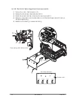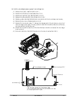
4.2.3.23 M32 Board (Main Board)
(1) Remove the scanner. (See Subsection 4.2.1)
(2) Remove the left side cover (See Subsection 4.2.3.1)
(3) Remove the right side cover (See Subsection 4.2.3.2)
(4) Remove the plate shield front (See Subsection 4.2.3.16)
(5) Detach all connectors connecting to the M32 board (main board).
(6) Remove the rear cover. (See Subsection 4.2.3.3)
(7) Remove the low voltage power supply (See Subsection 4.2.3.22)
(8) Remove seven (five) screws (silver) and two screws (silver) to remove the M32 board (main
board) .
View A
View A
×
7
Only C3530
HEAT
IDUP
HOP
HSDL
FSNS
DCID
SSNS
OP732
OP724
BELT
HVDLT
RSNS
CN1
PO
W
Note:
Numbers of screws
C3530 ....... 7
C3520 ....... 5
90
Service Manual
Y108500-4


