


94MS20 Rev. B4
5-13
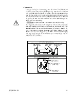
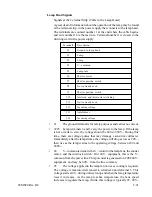
Shutter
The shutter is controlled by the PC board, with information from a switch
in the lamp head to provide position information. During cool-down and
exposure, the shutter is open and during warm-up and idle, the shutter is
closed.
The PC board compares the shutter position with the requested position.
The shutter motor will run until the switch position matches. The shutter
motor has a brake that is magnetically operated. Whenever the power is
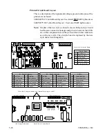
released from the motor, the brake falls into a slot. There is an LED on
the PC board that lights whenever the shutter is being energized. (Look
in the PC board pin section for a diagram of the LEDs).
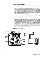
Shutter Switch
The switch provides shutter position information to the PC board. This
switch is in the lamp end where the cable enters, inside the manifold
cover. The cam is in the chamber with the shutter. A failure of the switch
can cause the shutter to rotate continuously or erratically. Similar
problems may be due to the shutter motor brake, the idle setting, or the
PC board.
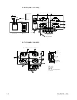
The switch contacts close when the shutter is fully open and remain closed
until the shutter closes. This level can be measured on the terminal strip
from terminal 9 (+) to terminal 7 (-). The level is 12 VDC when the
shutter is closed, and 0 V when the shutter opens. The switch is in the
lamp head on the end where the cable enters inside the air manifold on
older units. On newer units we use the normally open contacts, COM
contact and the center contact. We use the normally closed contacts, the
two outside leads, not the center contact. This switch is adjustable on
older units. We recommend scribing a line around the switch and the
bracket, if replacement is necessary, to return to the same position. The
switch roller should be centered on the cam and closed when the cam
pushes the wheel on the switch halfway.
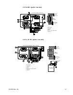
Shutter Brake
The motor that drives the shutter has a brake that is magnetically operated.
When the motor core magnetizes, it pulls a lever to release the brake. If
the shutter coasts or rotates continuously, look at the shutter LED on the
PC board. On early boards, where there are three LEDs in a row near the
front of the power supply, it is the third from the front of the power
supply. On the newer models, there are five in a row; it is the fourth from
the front of the power supply. When this light goes out, the shutter brake
should engage. If the shutter coasts, the brake may have failed. The shutter
may coast to the point where the switch will switch again to cause the
motor to energize. The LED on the board will flash if this occurs.
Содержание OLITE
Страница 1: ...94MS20 Rev B4 OLITE OLITE 60Hz Printing Light Service Manual O...
Страница 8: ...1 2 94MS20 Rev B4...
Страница 20: ...3 10 94MS20 Rev B4...
Страница 56: ...5 30 94MS20 Rev B4...
Страница 86: ...7 22 94MS20 Rev B5...
Страница 108: ...9 20 94MS20 Rev B4...
Страница 118: ...O Corporation 1850 East Saint Andrew Place Santa Ana Ca 92705 U S A Tel 714 258 5600 Fax 714 258 5601...


