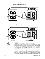


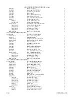


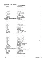


9-18
94MS20 Rev. B4
idle temperature of the lamp affects its life and reliability. If the idle
setting is too low (too far clockwise), the lamp will be slow to come to
power for exposures, and the unit may initiate a warm-up cycle. For
these reasons, please take care when making this adjustment and check
all other problems first.
Blower
The lamp blower is controlled by the P.C. board to provide the correct
cooling to the lamp. During warm-up the blower is off. At idle and
during low and medium power exposures the blower will vary in speed.
At high power exposure and during cool-down, the blower runs at full
speed.
A symptom of a defective blower would be: after the light is on for a
short period of time, the lamp extinguishes and requires 2 to 4 minutes to
restart. The heat causes the thermostat to open (see Interlock System).
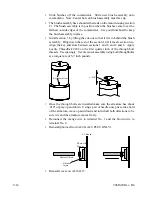
To test the blower, turn the light on and then off. This will put the light
source into a forced cool-down cycle. During the cool-down cycle, place
a piece of paper over the intake vent located on the opposite side of the
light from where the control cables enter. If the paper does not get pulled
to the vent the blower is suspect.
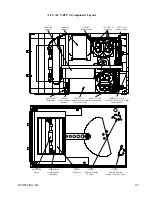
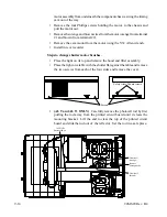
To replace the blower see COVER REMOVAL.
Blown Fuse
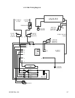
The P.C. board drives several circuits: THE BLOWER, SHUTTER
MOTOR, and the SHUTTER POSITION SWITCH. To find the cause
of a blown fuse unplug the light and remove the cover (see Cover
Removal). Disconnect the blower, shutter motor, and the shutter position
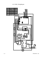
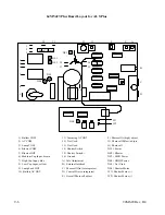
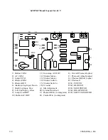
switch (see P.C. Board Layout).
Plug the unit in and turn on the power for 10 seconds. If the fuse blows,
the problem is the P.C. board. If not, unplug the light and reconnect the
shutter motor wires. Plug in the unit and turn it on, the shutter should
now operate. If the fuse blows, the problem is in the shutter motor or
wiring to the motor. Repeat these steps with the shutter position switch
and the blower.
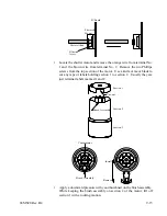
Photocell
The photocell is located on the P.C. board. Light is transmitted to the
photocell by a glass rod that travels the length of the unit from the reflector.
This rod is covered to keep dust from accumulating on it. If it becomes
necessary to remove the rod, do so carefully. If the rod gets broken, light
will not transmit properly and the photocell will not get enough light in
order to operate properly.
There are three adjustments for the photocell, overall photocell, photocell
A(high), and photocell B(low)(see P.C. Board Layout). The overall
photocell calibration is adjusted at the factory and is rarely necessary in
the field. The photocell A and photocell B are coarse adjustments, fine
adjustments should be made at the integrator.
Содержание OLITE
Страница 1: ...94MS20 Rev B4 OLITE OLITE 60Hz Printing Light Service Manual O...
Страница 8: ...1 2 94MS20 Rev B4...
Страница 20: ...3 10 94MS20 Rev B4...
Страница 56: ...5 30 94MS20 Rev B4...
Страница 86: ...7 22 94MS20 Rev B5...
Страница 108: ...9 20 94MS20 Rev B4...
Страница 118: ...O Corporation 1850 East Saint Andrew Place Santa Ana Ca 92705 U S A Tel 714 258 5600 Fax 714 258 5601...


