


AH6 Robot Maintenance Manual
Document Version V1.1.2 (19/09/2022)
53
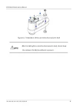
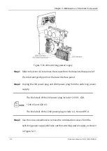
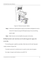
Figure 5-10 Removal of fastening screws
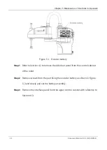
Step 4
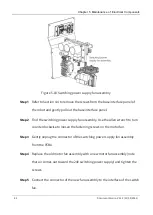
Install a new surge protection PCBA on the part in the base and tighten the
screws, and then connect all cables to the new surge protection PCBA.
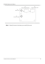
At the time of installation, users shall check whether the interfaces
match the line labels to avoid damage to the controller due to
wrong connection. Line labels corresponding to each interface are
shown in the figure below:
Step 5
Refer to Section 4.4 to reinstall the base interface panel on the robot.
Содержание AH6
Страница 1: ...AH6 Robot Maintenance Manual Document Version V1 1 2 19 09 2022 I...
Страница 16: ......
Страница 83: ...AH6 Robot Maintenance Manual Document Version V1 1 2 19 09 2022 67...


