Ohkura RM10C Скачать руководство пользователя страница 26

25


HXPRM10mnC0001E 

(5) Loosening the chart paper 

     The chart paper may not be proper fed, if it is stuck at perforations.  Be sure to loosen the paper.


Fig. 5.5


 Loosening the Chart Paper 


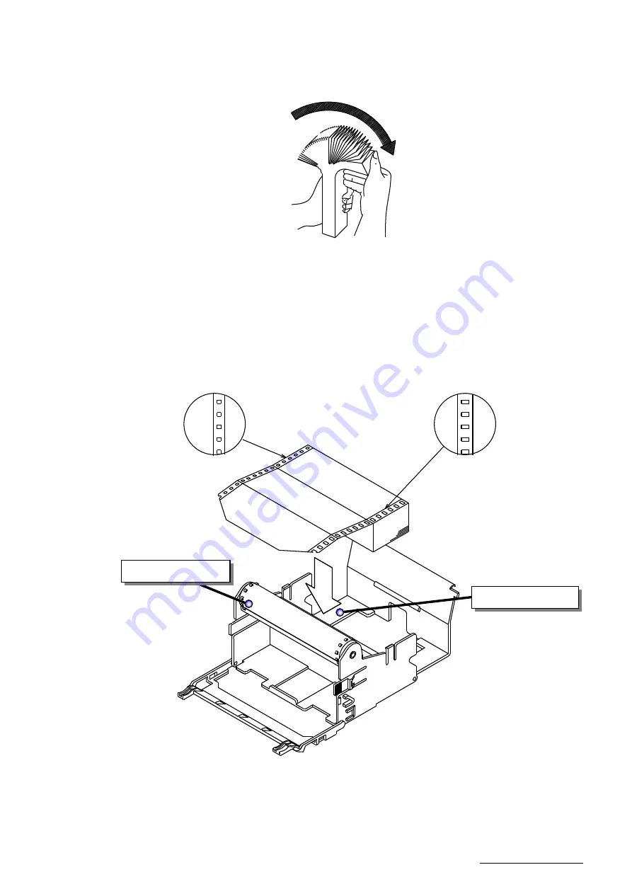
(6) Setting the Chart Paper into the Storage Chamber 

     Unfold the chart paper by two plies.  Holding the printing surface upward, set it in the storage  

     chamber. 


Fig. 5.6


Setting the Chart Paper 

Square Holes to Left 

Sprocket Drum 

Storage Chamber 

Rectangular Holes to Right 

Содержание RM10C

Страница 1: ...RM10C HYBRID RECORDER MULTIPOINT TYPE RECORDER INSTRUCTION MANUAL HXPRM10mnC0001E NOV 2015 5th Edition Copyright 2000 2015 Ohkura Electric Co Ltd All Rights Reserved...

Страница 2: ...system is expected by the error occurs due to external factors or failure the instruments take precautions to ensure the overall safety of your system 3 Take precautions to so that an alien substance...

Страница 3: ...arefully by the instrument 5 When the manual is lost or stained contact our sales representative 6 It is prohibited to copy or reproduce this manual without our permission 1 When installing this instr...

Страница 4: ...g information in this manual Symbols used on this manual WARNING Failure to observe this information could result in death or injury Be absolutely certain to read this CAUTION Failure to observe this...

Страница 5: ...ineering List Print 37 6 4 4 Record Start End Print 39 6 4 5 DI Manual Print 39 6 4 6 DI Date Time Print 39 6 4 7 DI Comment Print 40 6 5 Changing the Display 41 6 5 1 Auto Display 41 6 5 2 Manual Dis...

Страница 6: ...corder Dose not Work at All 102 10 1 3 When there is a Big Error 103 10 1 4 When the Trend Recording Deflected 103 10 1 5 When Records Nothing 104 10 1 6 When Recording is Faint 104 10 1 7 When the Ch...

Страница 7: ...e Following accessories should be attached Chart paper Ribbon cassette Mounting bracket Instruction manual Packing Fig 1 1 Accessories Table 1 1 List of Accessories No Part Name Type Quantity Remarks...

Страница 8: ...nameplate is affixed to the middle far side of the instrument Make sure that this instrument meets your requested specification seeing the following tables Table 1 2 Type 06 6 Multipoint type recorde...

Страница 9: ...environment may damage the appearance functions and service life of the instrument Storage Environment Aplace with little dust Aplace free from combustible explosive or corrosive gases SO2 H2S etc Apl...

Страница 10: ...9 HXPRM10mnC0001E 2 CONSTRUCTION 2 1 Appearance Fig 2 1 Appearance Ribbon cassette Door Chart holder Display keyboard Terminal block Printer Case Mounting bracket Indication card...

Страница 11: ...V W X Y Z RUN ALM CH No DATA RUN MENU PRINT FEED ENT ESC Alarm Type Display Indicates an alarm type in red H is illuminated when the alarm is High And L is illuminated when the alarm is Low Neither o...

Страница 12: ...int and change to the setting mode ESC key ESC function Exits that menu halfway selecting a function PRINT key PRINT function Used to perform manual print or list print key function Used to select a s...

Страница 13: ...er than the parenthesized dimensions per unit 128 128 7 max Panel thickness 25 150 56 144 144 3 5 2 5 100 200 min 200 min 138 1 0 138 1 0 RUN ALM RUN MENU PRINT FEED ESC CH NO DATA 137 137 L N 1A 2C 2...

Страница 14: ...AUTION Install the instrument in the following places Aplace free from where humidity often changes Aplace of normal temperature 25 or so Aplace exposed to as little mechanical vibrations as possible...

Страница 15: ...IP65 Prior to mounting the instrument to the panel attach a packing to the position shown in the figure The rest of the procedure is the same Fig 3 4 Mounting to the Panel in compliance with the IP65...

Страница 16: ...I 2 DI 1 WARNING In order to prevent an electric shock be sure to provide protective grounding prior to turning on the instrument Do not cut a protective grounding conductor or disconnect protective g...

Страница 17: ...ounding conductor there may be an effect caused by noise coming from the grounding conductor It is recommended not to share it with other instrument In order to comply with the requirements of safety...

Страница 18: ...ecommended to use a shielded input line For Pt 100 JPt 100 50m max When it is likely to be affected by induction noise particularly when wiring near the high frequency power source it is recommended t...

Страница 19: ...4 5 Page 19 3 Put back the transparent protective cover Fig 4 4 Input Wiring mV V TC CAUTION The transparent protective cover should surely remove the left and right both sides hooks simultaneously If...

Страница 20: ...istor to the input terminal block of the instrument Input accuracy is effected with the shunt resistor Use the following recommended resistor Resistance 250 Rated power 1 4W Tolerance 0 1 max Temperat...

Страница 21: ...a voltage to a DI input terminal from the outside ADI input contact capacity should be a withstand voltage of 50V DC 16mAor more ON resistance of 20 max Wiring resistance included Do not use unused t...

Страница 22: ...n 6C 6A Relay No 6 Normally open L N 1A 1C 2A 2C 3A 3C 4A 4C 5A 5C 6A 6C DI1 DI2 DI3 DI COM COMMON for DI1 to DI3 L N 1A 2C 2A 1C 3A 4C 4A 3C 5A 6C 6A 5C 4 B 4 B 4 A 5 B 5 B 5 A 6 B 6 B 6 A 1 B 1 B 1...

Страница 23: ...stance Rt 200 to a host computer side Connection is a maximum of 32 sets including a host computer Cable length is a maximum of 1 2 km Use the UL20620 SB M cable made by HITACHI CABLE LTD or equivalen...

Страница 24: ...to ensure proper recording If the chart paper holder is taken out with recording operation being activated the ink ribbon may be damaged To replace the chart paper be sure to press the RUN key to sto...

Страница 25: ...to this side Fig 5 3 Taking out the Chart Holder 4 Opening the Chart Cover and Chart Guide Open the chart guide and the chart cover outwardly Fig 5 4 Opening the Chart Cover and Chart Guide Pull out t...

Страница 26: ...ure to loosen the paper Fig 5 5 Loosening the Chart Paper 6 Setting the Chart Paper into the Storage Chamber Unfold the chart paper by two plies Holding the printing surface upward set it in the stora...

Страница 27: ...ligning the Chart Paper with Sprocket Drum Chart Holder Sectional View 8 Closing the Chart Cover and Chart Guide Close the chart cover and the chart guide in the arrow directions Fig 5 8 Closing the C...

Страница 28: ...to feed the chart paper by 4 plies Fig 5 9 Checking Paper Feed 10 Putting Back the Chart Paper Holder Push in the chart holder horizontally into the case until it is locked Fig 5 10 Putting Back the...

Страница 29: ...keyboard to feed the chart paper Fig 5 11 Pressing the FEED key 13 Pressing the RUN Key to Restart Operation UN CH No DATA UN The chart paper is fed while pressing the key Releasing the key stops pape...

Страница 30: ...take out the ribbon cassette to the front Fig 5 12 Taking Out the Ribbon Cassette CAUTION If the chart holder is taken out with recording operation being activated the ink ribbon may be damaged To rep...

Страница 31: ...into the ribbon holder until the latch clicks When the ribbon feed shaft is not easily fit in turn the gear to the direction of an arrow to adjust the position When this is done push the ribbon casset...

Страница 32: ...mode before the power OFF Fig 6 1 Display Screen at Power on RUN ALM Note When electric power failure occurs the initialization is performed after power recovery And it becomes the above initial stat...

Страница 33: ...cording 6 3 2 Feed the Chart Paper The chart paper is fed while the FEED key is pressed and stops when released CAUTION The instrument checks zero point for every recording If the printer block is man...

Страница 34: ...on the end of the last printing This mark is meaning of that over items would not be printed For priority of respective printing see next page Priority in Reference Date Time Process variable Prints i...

Страница 35: ...tion remains effective If an alarm is activated while manual print is running alarm print will be performed when recording restarts Reference Printing is actuated in following priority See following P...

Страница 36: ...number range scaling value engineering unit Setting alarm type 1 List print operating procedure Press the PRINT key Use the PRINT key to display and press the ENT key Use the PRINT key to select Press...

Страница 37: ...10 000 3 10V 10 000V 10 000 4 10V 10 000V 10 000 5 TYPE K 200 00 100 00 6 10V 10 000V 10 000 CH ALARM1 RLY ALARM2 RLY ALARM3 RLY ALARM4 RLY UNIT 1 H 8 000 L 5 000 V CH DIGITAL ZONE mm PARTIAL 1 ON 0...

Страница 38: ...ey to select Pressing the ENT key executes engineering list print Once engineering list print starts the display is automatically returned to the Data Display screen Upon termination of engineering li...

Страница 39: ...OFFSET COLOR 1 OFF INT 0 0 PRP 2 OFF INT 0 0 RED 3 OFF INT 0 0 GRN 4 OFF CH 0 0 BLU 5 OFF EXT 798 0 0 BRN 6 OFF CH CH5 0 0 BLK COM_ADR SPEED DATA PARITY STOP 01 9600bps 8bit NONE 1bit DI 1 OFF 2 OFF 3...

Страница 40: ...Print option DI manual print prints measurements and time on paper by turning on DI The content of the print is the same as 6 4 1 Manual Print 1 DI function of the engineering mode is set Please refer...

Страница 41: ...to the setup mode 1 DI function of the engineering mode is set Please refer to 7 2 9 DI Functions for details Date Time print is synchronous print Date Time print is asynchronous print 2 DI is operate...

Страница 42: ...uentially at intervals of 2 5 seconds 6 5 2 Manual Display Displays the process variable of specific channel it updates every measurement cycle The data is the same as Auto display Pressing the ENT ke...

Страница 43: ...from the setup mode to the recording mode user mode press the MENU key for 3 seconds or more again The following describes how to set the following items The following shows a display map of the setu...

Страница 44: ...ansion Digital Print Tag Comment Words Shift to the engineering mode Printing Cycle Zone Recording Partial Compression Expansion Digital Print Tag Comment Words Setting Mode Setting Copy from Channel...

Страница 45: ...Engineering unit all channels BF 43 00 Chart speed 1 20mm h 2 20mm h Time 2000 01 01 00 00 Sets up the present time Japan standard time GMT 09 00 Dot point interval 10 s Zone setting all channels 0 1...

Страница 46: ...nnel sum difference average mode to Unnecessary channels can be skipped mode Setting Channel Mode Key Voltage Current key Thermocouple Resistance temperature detector Scaling Square root Decade Differ...

Страница 47: ...n and numeral Use the key to shift a digit Press the ENT key Use the key to select a sign and numeral Use the key to shift a digit Press the ENT key Press the ENT key Setting is completed To return to...

Страница 48: ...e In the or mode press the ENT key to select the range Use the key you can select the type out of the range ENT key 10mV 0 20mV 0 50mV 200mV 1V 0 5V 10V 4 20mA Range Mode B R S K E J T C Au Fe N PR40...

Страница 49: ...the key to select a range 50 mV Press the ENT key Use the key to select a numeral Use the key to shift a digit Press the ENT key Use the key to select a numeral Use the key to shift a digit Press the...

Страница 50: ...ENT key Use the key to select a numeral Use the key to shift a digit Press the ENT key Press the ENT key Setting is completed To return to the user mode hold down the MENU key for 3 seconds or more No...

Страница 51: ...a numeral Use the key to shift a digit Press the ENT key Use the key to select a numeral Use the key to shift a digit Press the key again in the lowest digit right end to blink a decimal point Use the...

Страница 52: ...caling upper limit value Scale R IN Input voltage OUT Output Scaling value When an input value is 1 or more 1 to 100 OUT SCAL R SCAL L SCAL L When an input value is less than 1 OUT IN SPAN L SCAL L Ex...

Страница 53: ...the key to shift a digit Press the ENT key Use the key to select a numeral Use the key to shift a digit Press the ENT key Use the key to select a numeral Use the key to shift a digit Press the ENT key...

Страница 54: ...owing relational expression OUT1 IN OUT 10 OUT1 LG SCAL L Log10 SCAL L LG SCAL R Log10 SCAL R Example When makes setting in previous page the display is as follow table Input voltage V Display LG SCAL...

Страница 55: ...n to the user mode hold down the MENU key for 3 seconds or more About Difference Sum and Average The channel to be set must be larger than the one on which computes the difference sum or average When...

Страница 56: ...ss the ENT key Setting is completed To return to the user mode hold down the MENU key for 3 seconds or more Note Setting all the channels to Skip displays an error At least one channel should be set t...

Страница 57: ...arm set value of 2 000 and alarm output relay No 1 Hold down the MENU key for 3 seconds or more to enter the setup mode Use the key to display Press the ENT key Use the key to select the channel you w...

Страница 58: ...ess the ENT key If the alarm output is set to ON set the relay number Use the key to select the relay number out of 1 to 6 and press the ENT key Press the ENT key Setting is completed When you want to...

Страница 59: ...character in the same manner When the number of unit characters is less than 6 enter a code to end Press the ENT key Press the ENT key Setting is completed To return to the user mode hold down the MEN...

Страница 60: ...59 HXPRM10mnC0001E 1 Character Code Table Example The code number for C is 43...

Страница 61: ...mode Use the key to display and press the ENT key Use the key to select the 1st chart speed and press the ENT key Use the key to set the 1st chart speed and press the ENT key Press the ENT key To retu...

Страница 62: ...tion of printing by chart speed When the chart speed is 0 h it s printed with forcible chart feed When the chart speed is more than 120 h not printing as shown the Table above List Print Engineering L...

Страница 63: ...to Channel 2 Hold down the MENU key for 3 seconds or more to enter the setup mode Use the key to display and press the ENT key Use the key to select the copy from channel and press the ENT key Use th...

Страница 64: ...t Specify with ON OFF whether the measured data for each channel is to be printed or not Tag Set the tag which is to be printed instead of a channel number for logging print or manual print Setting up...

Страница 65: ...s the ENT key Use the key to display and press the ENT key Use the key to select the channel you want to set and press the ENT key Set a zero point printing position in percentage Use the key to selec...

Страница 66: ...Set a boundary point position in percentage Use the key to select a numeral and use the key to shift a digit Press the ENT key Set a boundary point position to 0500 0 Use the key to select a numeral a...

Страница 67: ...and press the ENT key Use the key to select the channel you want to set and press the ENT key Use the key to switch from to and press the ENT key Press the ENT key Setting is completed To return to t...

Страница 68: ...through 4th characters in the same manner Set as the 5th character and press the ENT key Press the ENT key Setting is completed To return to the user mode hold down the MENU key for 3 seconds or more...

Страница 69: ...as setting the 1st character Repeat setting for each channel Press the ENT key Setting is completed To return to the user mode hold down the MENU key for 3 seconds or more Note When the number of comm...

Страница 70: ...Press the ENT key After reset enter the engineering mode The following describes how to set the following items The following shows a display map of the Enginneering mode Use the key to operate 7 2 1...

Страница 71: ...chronous Comment 2 print Asynchronous Comment 3 print Asynchronous Manual print Asynchronous Date and time print Asynchronous Setting DI No Function Purple Red Green Blue Brown Black Setting Channel C...

Страница 72: ...Scale print Logging print Sync Async Record Start end print INT Ch OFF ON 6H 00 00 OFF Sync print OFF Use the RUN key COM communication Protocol Address Baud rate Data length Parity bit Stop bit Origi...

Страница 73: ...splay and press the ENT key Use the key to display and press the ENT key Use the key to select and press the ENT key 7 2 3 Channel Offset For channel offset setting set the value to be added to an act...

Страница 74: ...l junction box CH Channel input compensation Internal compensation INT has been initially set Example When setting the external compensator s temperature constant voltage for Channel 6 to 391 V Input...

Страница 75: ...ting 7 2 5 Changing the Printing Color Change a printing color can be changed for each channel Example When setting the black color as a printing color Enter the engineering mode See the key operation...

Страница 76: ...and press the ENT key Setting is completed Returned to the Recording Start Stop Setting screen 2 Tag channel print selection In case of logging print or manual print set whether a tag or channel shou...

Страница 77: ...the key operation in page 69 Use the key to display and press the ENT key Use the key to select and press the ENT key Use the key to display and press the ENT key Setting is completed Returned to the...

Страница 78: ...nd press the ENT key Setting is completed Returned to the Logging print Setting screen 5 Scale print ON OFF Set scale print to ON OFF Example When setting scale prints to OFF Enter the engineering mod...

Страница 79: ...neering mode See the key operation in page 69 Use the key to display and press the ENT key Use the key to display and press the ENT key Select from Original Modbus RTU Use the key to display and press...

Страница 80: ...ter the engineering mode See the key operation in page 69 Use the key to display and press the ENT key Use the key to select and press the ENT key Use the key to display and press the ENT key Setting...

Страница 81: ...oint Enter the engineering mode See the key operation in page 69 Use the key to display and press the ENT key Use the key to select and press the ENT key The instrument starts to feed and print the ch...

Страница 82: ...t and press the ENT key The instrument starts to feed and print the chart paper With the left move and right move adjust the 100 mm position of the chart paper and the recording position Press the ENT...

Страница 83: ...r 35 mV After 10 seconds make sure that the ALM lamp unilluminates and press the ENT key Enter 55 mV After 10 seconds make sure that the ALM lamp unilluminates and press the ENT key Enter 200 mV After...

Страница 84: ...calibrate RTD for a channel the input terminals of the other channels are shortcut Recording requires RTD calibration for every channel Note During calibration ALM lamp displays following conditions b...

Страница 85: ...the ENT key 7 3 Terminating the Engineering Mode Example The following describes how to save the setting data Use the key to display and press the ENT key Use the key to select and press the ENT key...

Страница 86: ...peed etc Controlling of the recorder Partially Selection to print recording start stop and changing display etc For the functions to see the separate Communication Command Reference Manual charged 8 1...

Страница 87: ...function does not reply The data format error status can be confirmed by the ESC S command described later 4 Control codes ESC 1B HEX hexadecimal This code is used for an escape sequence such as openi...

Страница 88: ...and is received the recorder transfers the process variable data to the transmit buffer when the ESC T command is received 2 Updating the Data ESC Once this command is received the recorder transfers...

Страница 89: ...range Data S Skip All the data are spaces Data information 2 1 byte E Final data Space Other data to Alarm information 1 byte each 4 bytes in total H Upper limit alarm L Lower limit alarm Space Alarm...

Страница 90: ...LEVEL3L LEVEL H Upper limit alarm bit at the alarm level x LEVEL L Lower limit alarm bit at the alarm level x S Process variable data to 2 byte hexadecimal data The higher and lower bytes can be rever...

Страница 91: ...end channel to When the number of channels is one specify S_CH E_CH Example LF 01 06 CR LF The unit and decimal point of 01 to 06 channel output 4 Data Format Data information 1 1 byte N Normal D Dif...

Страница 92: ...s Output Command Receiving this command outputs the status for the command received so far 2 Status Output Table 8 1 Status output list Status factor Status output Status factor A D END Syntax error P...

Страница 93: ...esignation BO BINARY Mode only Close Command Open the Link Prepares For the Process Variable Data Output Prepares the Update Data Sends the Update Data Determines the Process Variable Data Output Orde...

Страница 94: ...inent function code if an error occurs during command transmission an error response is returned in the fixed format described in this section Example of slave response function code 06H command error...

Страница 95: ...s Component Data length Data Slave address 1 Function code 1 04H Data Relative start address high order 1 00H Relative start address low order 1 32H Read data count high order 1 00H Read data count lo...

Страница 96: ...30015 E Software version 7 16 7 30016 F Software version 8 16 8 30017 10 Software version 9 16 9 30018 11 Software version 10 16 10 30019 12 Software version 11 16 11 30020 13 Software version 12 16...

Страница 97: ...stops 1 During printing 30062 3D Reserve 30100 63 Reserve 30101 64 Channel status CH01 00bit Alarm 1 1 ON 0 OFF 01bit Alarm 2 1 ON 0 OFF 02bit Alarm 3 1 ON 0 OFF 03bit Alarm 4 1 ON 0 OFF 30102 65 CH02...

Страница 98: ...1 4 CH05 Current unit 30148 93 Unit 2 4 30149 94 Unit 3 4 30150 95 Unit 4 4 30151 96 Unit 1 4 CH06 Current unit 30152 97 Unit 2 4 30153 98 Unit 3 4 30154 99 Unit 4 4 30155 9A Reserve 8 3 5 Reading fro...

Страница 99: ...end recording deflected Are recording indication done properly Any big error in indicated values or dot printing position Any improper dot printing Any blurred dot printing or printout Proper printout...

Страница 100: ...reference With the apparatus left in the working conditions make adjustment according to the instructions in 7 2 11 Point Calibration See page 80 9 5 Calibration Data Calibration Calibrate a process...

Страница 101: ...Data Calibration Calibration of the resistance temperature detector See page 83 Note A resistance value should not disperse greater than 6 m from one wire to another When calibrate RTD for a channel...

Страница 102: ...dded a part for the difference with true value 0 5 as the right RJC temperature 24 5 0 5 25 0 Conduct calibration according to the instructions in 7 2 12 Data Calibration Calibration of reference junc...

Страница 103: ...r feed Inaccurate feed rate Flow chart 2 Page 103 Flow chart 3 Page 103 Flow chart 4 Page 104 Flow chart 5 Page 104 Flow chart 6 Page 105 Flow chart 7 Page 105 Contact our dealer where you purchased t...

Страница 104: ...correctly See 7 1 1 on Page 45 Contact our dealer where you purchased the instrument or our sales representative Flow chart 2 Big error Scaling set properly Calibration corrects initialized to the fac...

Страница 105: ...1 Set properly See 5 2 on Page 29 Ribbon fed properly Replace the ribbon cassette See 5 2 on Page 29 See 6 4 on Page 34 to 38 RUN mode selected Digital printout enabled Contact our dealer where you pu...

Страница 106: ...ting Turn on the DI contact See 7 2 9 on Page 79 Contact our dealer where you purchased the instrument or our sales representative Flow chart 7 Chart paper feed improper Chart cover locked properly Ch...

Страница 107: ...eading error Engineering data EEP READ3 Non volatile memory Reading error ADC Calibration data RJC ERROR The measurement is abnormal of the RJC internal temperature sensor Operation error Calibration...

Страница 108: ...ltiple errors are encountered their error numbers are displayed with automatic scrolling When an error restores an error display can be canceled to the input of the RUN key CAUTION While indicates an...

Страница 109: ...signal source resistance 10k max in mV TC input without burnout 100 max in mV TC input with burnout 1k max in Voltage input 10 max per line in Resistance temperature detector input Normal mode reject...

Страница 110: ...1 Power consumption 100V Max power consumption 6 dot recorder About 25VA About 30VA 11 1 5 Normal Operating Conditions Ambient temperature 0 to 50 Ambient humidity 20 to 80 RH Supply voltage 85 to 26...

Страница 111: ...etting accuracy Digital display accuracy 11 1 7 Low Voltage Directive and EMC Directive Low Voltage Directive EN61010 1 EMC Directive EN61326 1 Class A At the EN61000 4 3 test condition DC voltage DC...

Страница 112: ...E J T C N PL U L 0 5 Table 11 2 Measurement Range Type RANGE Measurement range Measurement Digital Analog Accuracy Max resolution Accuracy DC voltage DC contact Input 10 to 10mV 0 2 of rdg 3digits 10...

Страница 113: ...0 15 of rdg 1 328 0 to 1112 0 F 0 15 of rdg 0 7 F 328 to 148 F 0 15 of rdg 1 8 F K3 200 0 to 300 0 0 15 of rdg 0 3 200 to 100 0 15 of rdg 1 328 0 to 572 0 F 0 15 of rdg 0 5 F 328 to 148 F 0 15 of rdg...

Страница 114: ...to 572 F 67 7 F 572 to 1472 F 33 8 F PL 0 0 to 1390 0 0 15 of rdg 0 7 32 0 to 2534 0 F 0 15 of rdg 1 3 F U 200 0 to 400 0 0 15 of rdg 0 5 200 to 100 0 15 of rdg 0 7 328 0 to 752 0 F 0 15 of rdg 0 9 F...

Страница 115: ...igits Analog recording accuracy 4 1000 1000 10 digits 0 01V Example 2 When Type K is 0 0 200 0 and Scaling is 0 00 200 00 Range accuracy rating 0 15 200 0 0 3 Input 200 0 6 6 digits Scaling factor 10...

Страница 116: ...lay value Normally the accuracy rating is less than 1 digit and you cannot read by significant digit 4 Difference Sum and Average The accuracy rating of Difference Sum and Average is as following form...

Страница 117: ...0mm The length of the Clean Chart is 12 m Chart speed 0 1 2 3 4 5 10 15 20 25 30 40 50 60 75 80 90 100 120 150 160 180 200 240 300 360 375 450 600 720 750 900 1200 1500mm h Analog recording is not don...

Страница 118: ...Scaling print ON OFF Logging print Sync Async Alarm hysteresis Burn out DI function Option Affix print Prints Channel number by the analog recording Manual print Prints Measurement result by key input...

Страница 119: ...res that the effective number to indicate and print Alarm Print Prints Occurrence time Occurrence channel Setting No and Alarm type in purple at occurring an alarm Alarm Recovery Print Prints Recovery...

Отзывы: